Saturday, June 24, 2006

Odds & Ends

I took care of several miscellaneous leg-related tasks today.

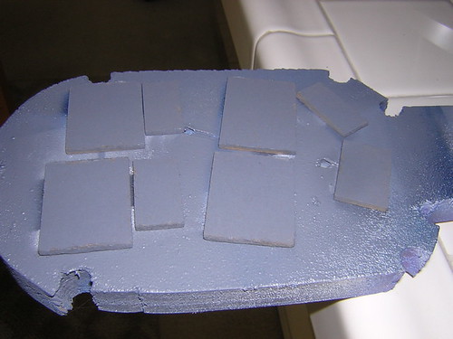
First, I applied primer to the MDF that will go in the armpits, where the under shoulder details go.


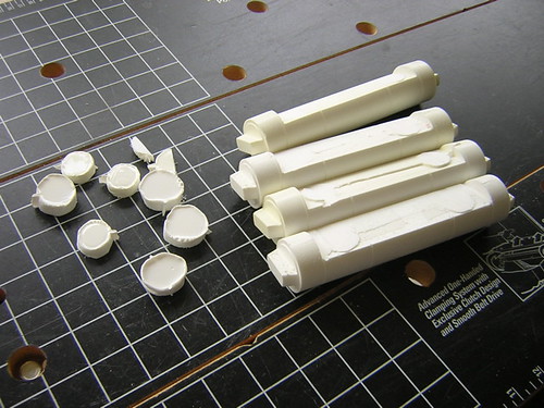
Next, I cut all the nubs off of the resin ankle cylinders, so that they will fit flat onto the ankles.


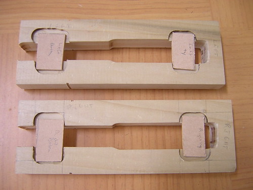
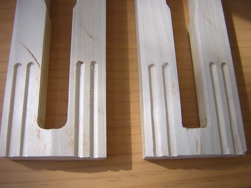
After that, I took a shot at cutting out the groove in the ankles. I drilled a 1/8" hole in each end of the groove (the blueprints don't specify the height of the groove, only the 1.875" width). Then I used the Dremel with the cutoff wheel attachment to cut the groove.
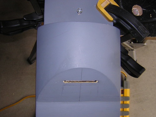


It turned out pretty ugly looking, but I think with some filing/sanding and wood putty where necessary, it should be okay.

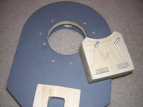
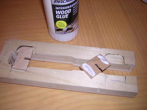
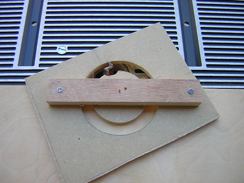
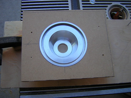
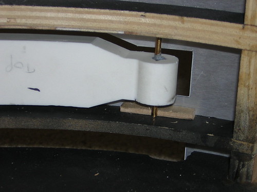
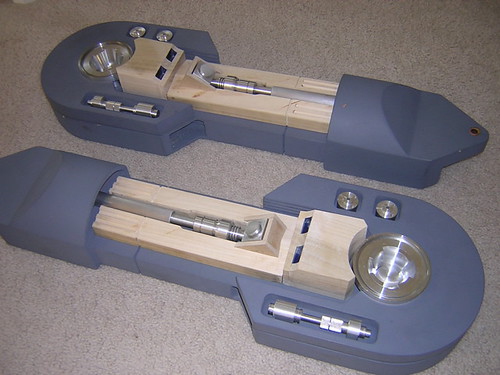
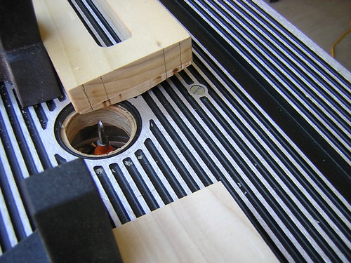
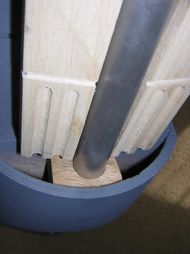
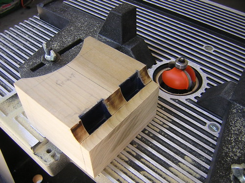
Finally, I made little platforms to support the leg struts from underneath. I used the router table to cut a circle of the proper radius of the inner ankle, and then I chopped a piece of that circle to size to fit in the ankle.

I used a 3/4" diameter Forstner bit to cut a circle about 1/4" deep to support the strut. I will need to glue this platform in place, but I'm waiting until I'm done cleaning up the groove in the ankle before I block my path to the backside of the groove.
Friday, June 23, 2006

Installed Top Shoulder Buttons

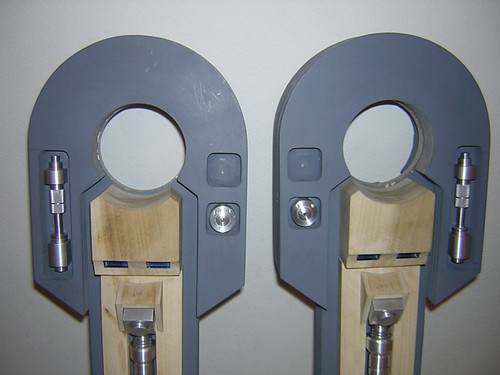
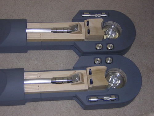
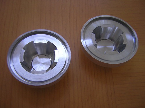
Tonight I was able to install the top shoulder buttons, and finish up the horseshoes (except for painting).

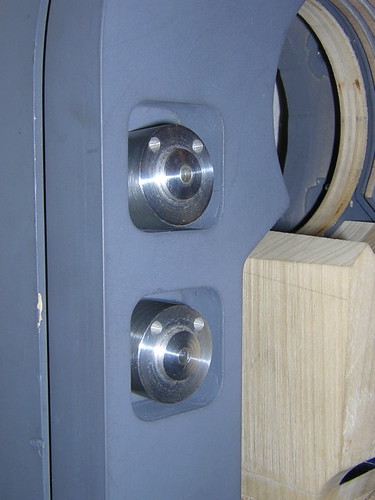
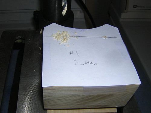
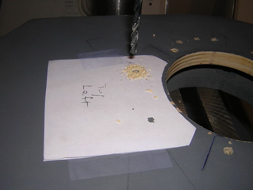
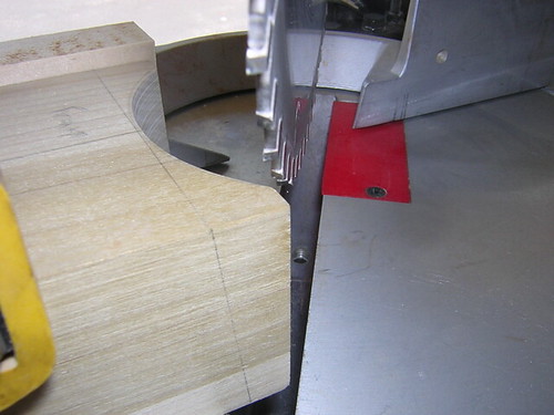
Based on the blueprints, I used some trigonometry to calculate the angle at which the top button hole should be drilled (five degrees). I tilted the drill press table, centered the bit, and drilled through the horseshoe, from the outboard side to the inboard side. I flipped the horseshoe upside down and rotated it 180 degrees, and countersunk the hole on the other side. Then I cut a #8 screw down to size and installed the button.


Next up: More leg work, including the slots in the ankles, a platform in the ankle to support the leg strut, and I still need to finish off the armpits where the under shoulder details go. Sounds like a busy weekend.

Thursday, June 22, 2006

Attached Booster Cover Bodies, Shoulder Hydraulics & Bottom Buttons

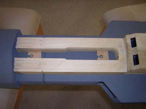
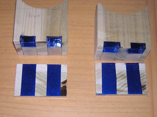
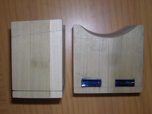
After the glue holding the MDF slots for the booster cover bodies had dried overnight, I was able to start attaching the booster cover bodies to the legs. Two screws per booster cover were all that were needed. I only had enough time to take care of one of the legs in the morning, I did the other in the evening.


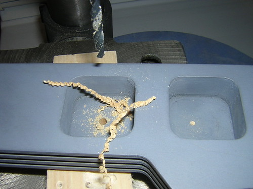
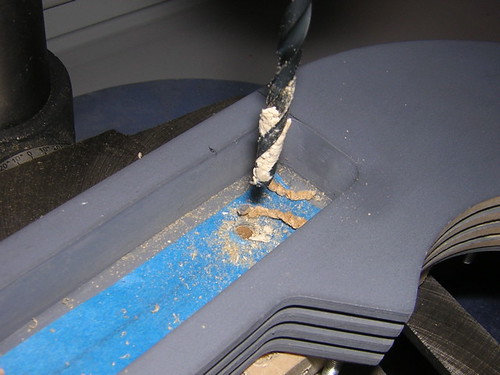
I also started drilling holes in the horseshoes to attach the bottom shoulder buttons, and the shoulder hydraulics.


For the shoulder hydraulics, I attached a piece of tape (same width and length as the hydraulic) to the back of the part, and then screwed a screw into each of the two holes in the back, making corresponding holes in the tape. Then I took the tape, centered it properly into the slot in the horseshoes, and used that as a guide for drilling.


Things seemed to turn out okay.


I didn't do the top shoulder buttons yet because those get installed at an angle, and I need to take the time to do that correctly.

Wednesday, June 21, 2006

Screws for Booster Cover Tops, MDF Glued In for Booster Cover Backs

Now that the shoulder hubs holes are complete, I was able to get to work on placing the booster cover assemblies below them.

I laid the tops of the booster covers down on plain paper and traced them, and then cut out the tracings. I taped the tracings onto the booster cover backs, and drilled holes through the paper and into the backs of the booster covers, for the screws (heads cut, off as usual) that will go into the legs to mount the booster cover tops.


Next, I took the tracings off of the booster cover tops, and used them to locate where on the legs I needed to drill corresponding holes. I placed the main portion of the booster covers down, and then centered the tracings under the shoulder hub holes, as the bottom of the tracings sat down against the tops of the main booster cover bodies for each leg.

Once I was happy with the location of the tracings, I taped them down, took the legs to the drill press, and drilled the holes in the legs through the pre-existing holes in the paper tracings.


Even if these holes had mismatched slightly, it would not have been tragic, as they can be widened a bit. Since the screws will have nuts holding them in, they can be scooted over a bit without complication.

I inserted the screws in the backs of the booster cover tops, and gave test fittings. Luckily, all went well.


Finally, I glued down the MDF mounting slots for the main booster cover bodies. Hopefully I can screw those down in place tomorrow.

Tuesday, June 20, 2006

Cut Shoulder Hub Hole in Right Leg

I only had 1/2 hour after work to get anything done, but that was enough time to successfully cut the shoulder hub hole in the right leg. Like the left leg, the hole and the aluminum shoulder hub fit well, and the hole is directly centered in the horseshoe.

Phew! Glad that's behind me.

Monday, June 19, 2006

Cut & Routed Left Shoulder Hub Hole, Installed Painted Utility Arms

The stakes just keep getting higher as work continues on the legs. It was time to cut and route the shoulder hub hole. If I messed this up, it probably would have ruined the leg. I actually felt a bit queasy as I started work.

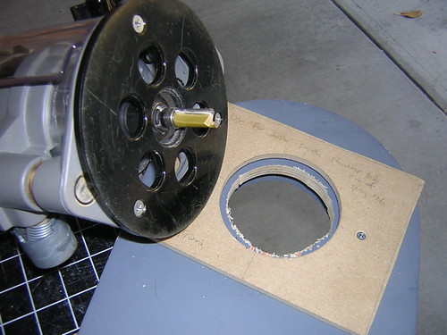
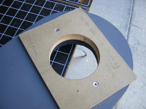
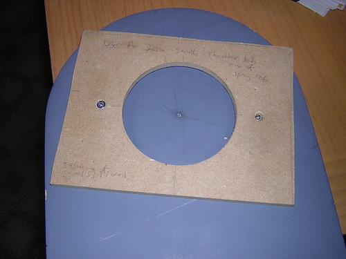
First, I rough-cut the shoulder hub hole, in preparation for routing the hole to size with the router. The flush-cut bit used for the routing has the bearing on top, to ride along the inside of the MDF template that is screwed down to the top of the leg.


I routed the hole to size, and could finally exhale. The cut ended up just the way I needed it to be.


Once I unscrewed the template, I test fitted the hub in the leg. It fit pretty well, so I'm happy with it. More important, the hole for the hub is exactly centered in the horseshoe opening, which is what I was really stressing over.


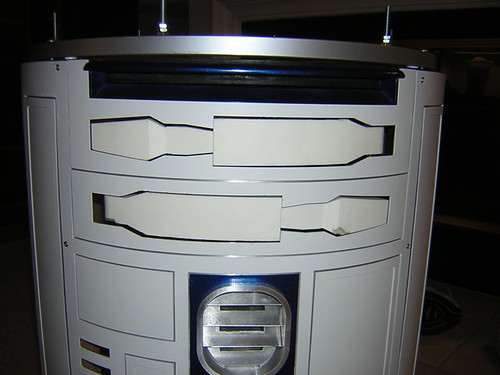
Now that the paint has thoroughly dried on the utility arms, I was able to reinstall them in the body. I still don't like how far back the pivot point of the bottom arm sits, I may have to figure out a way to correct that some time later.


I wrapped up by preparing the right arm for shoulder hub hole cutting, I may not be able to get to that until Wednesday. We'll see.

Sunday, June 18, 2006

Tested Shoulder Hub Template, Mounted Template to Arm

Not much at all got done today due to other commitments.

I tested my shoulder hub template on some 1/2" scrap plywood, the same kind that makes up the top layer of the legs that I will be cutting and routing. I'm glad I tested, because I found that my "final" template from yesterday made a hole in the plywood that was a bit too snug for the aluminum hub to fit through. I went to my next larger template, and found that when I used it on the plywood, the fit of the aluminum hub was nice and snug, so I'll be using that template.

Next, I spent a lot of time trying to locate exactly where on the left leg to locate the template. I did this repeatedly, by installing the horseshoe on the leg, drawing an outline of the partial circle that the inner part of the horseshoe forms, and then trying to center the template within the horseshoe's partial circle. A couple of times I thought I had it, and screwed the template down, only to discover it was slightly off. So I'd unscrew the template, rotate it slightly, and try again.

I tried a few different strategies for centering, including drawing concentric circles from a common centerpoint, but whenever I mounted the template, I'd find that I was off by maybe a millimeter. Finally, with the horseshoe mounted, I used a ballpoint pen to trace the outline of the partial inner circle. The line was offset a small distance from the edge of the horseshoe, and that provided the guidance I needed to center the template where it should be (I hope).


I still have to go through all this again with the right leg, and I need to jigsaw-out a rough cut on the legs before I can actually use the template. I'm going kind of slow here, because I really need to get this right, or the hub won't easily come out of the arm.

Saturday, June 17, 2006

Painted Utility Arms, Cut Shoulder Hub Template

Today I painted the utility arms. I enjoyed it so much, I painted them twice. The first time I dropped them on the lawn. D'oh!! After a soaking in acetone and a cleaning, I repainted them later in the day.


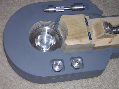
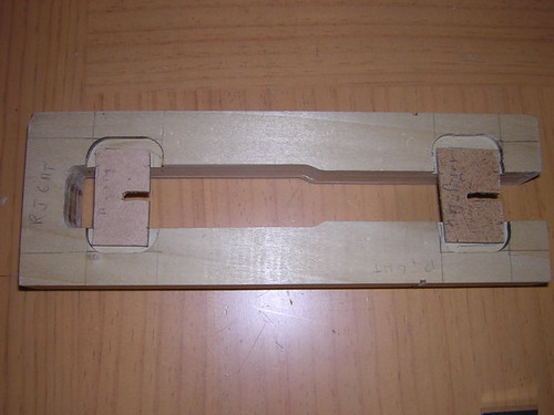
I also cut out my MDF template for routing the shoulder hub holes to size in the legs (I still need to do the rough-cut in the legs first). The hub fits snugly in the template, just the way I want it. I will nail the template to the leg, and use a flush-cut bit to finish the shoulder hub hole in the leg after I have rough-cut it.

It actually took me three tries to get the hole the perfect size (twice I went a hair too wide on the radius), but I had anticipated that on this template.


Friday, June 16, 2006

Shoulder Hub Template Prep, JB Welded Servo Rods in Utility Arms

In the morning I did a little work in preparing my shoulder hub template for cutting tomorrow. This is mainly an experimental template, I don't fully expect that the hubs will fit perfectly on the first try. We'll see.

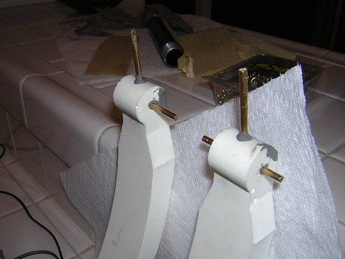
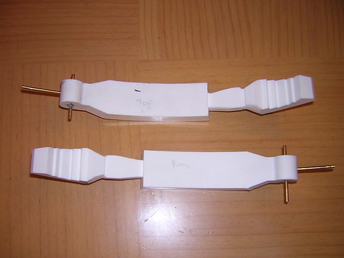
In the evening I trimmed the rods that will go in the ends of the utility arms for the servos that will open the arms, and JB Welded the rods into place.

The JB Weld that looks like it dripped in other areas is actually left over from when I was filling in small gaps and voids in the resin, when I JB Welded in the pivot rods.

Wednesday, June 14, 2006

Finished Installing Bottom Utility Arm

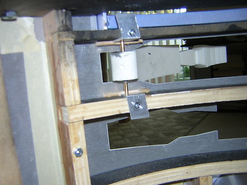
This morning I glued in the remaining MDF to support the bottom utility arm, and this evening I drilled and screwed down the aluminum channel to hold it in place.


Hmm. The pivot point of the bottom arm seems to be sitting a bit deeper into the body than I intended. I may have to live with it, as the pivot rod's MDF-half of the support is glued down now.

Tuesday, June 13, 2006

Finished Mounting Top Utility Arm

I was able to drill the aluminum channel and secure the top utility arm today. Recall that the rod running through the pivot point of each utility arm is held in by MDF and aluminum channel. The MDF and aluminum channel both have half of a 1/8" circle drilled out of them (thus making a circle), in which the 1/8" rod rests. The two materials squeeze together around the rod.


Hopefully I can make some progress on the bottom utility arm tomorrow.

Monday, June 12, 2006

Finished Booster Cover MDF Notches, Utility Arm Work

I finished notching the last two pieces of MDF for the booster cover mounts (they look just like yesterday's work).

With the dome and legs removed, I turned the body upside-down and glued in the upper piece of MDF that will hold the top utility arm in place. It was mildly amusing to have R2 upside down and be able to spin him around on the lazy susan Rockler bearing (evidently, I'm easily amused).


I also drilled holes in the ends of the utility arms for the servo arm bars that will protrude from them. These are the bars from this past Saturday that have a tiny hole drilled at the ends. I haven't JB Welded the bars in place yet, I probably need to shorten them up a bit first, so they don't run into any internal vertical ribs.

Sunday, June 11, 2006

Notches for Booster Cover MDF Started

Talk about having hardly anything to report...

I started cutting the notches in the MDF that will help support the booster covers on the legs. I'm so lame, I had to redo these a couple of times! Getting the width just right, and getting the cut straight, appears to be beyond my competency.

I still have to cut the notches on the MDF for the other leg. I'm planning on using #8 3/4" wood screws to fit in the notches.


Part of the reason I got so little done today is that I ran up to Mike Senna's, to discuss how to cut the holes in the legs for the shoulder hubs. This is actually very tricky and somewhat complicated. I'll explain in more detail when I get there, hopefully by next weekend.

Saturday, June 10, 2006

Finished Cutting Booster Covers, Utility Arm Work

Today I was able to finish cutting the booster covers. They are nearing completion.

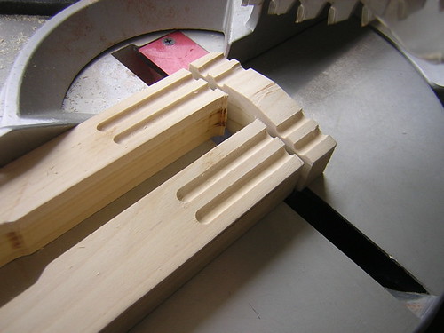
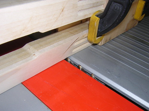
First, I chopped off the bottoms of the booster covers, finally opening up the "tuning fork."


Next, I cut the grooves in the booster cover bodies to match the grooves in the legs.


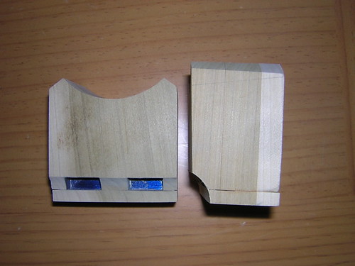
I wrapped up the cutting by routing areas in the back of the booster covers to accommodate the mounting of them on the legs. The plan is to glue down MDF in the routed areas, and then put a partial slot in the MDF, that will allow the booster covers to hang from screws in the legs. Picture a phone mounted on a wall and you should get the idea.


Of course, I had to dry-fit everything together to see how it looks. I haven't cut the holes in the legs for the shoulder hubs yet, so they just sit on top for now.


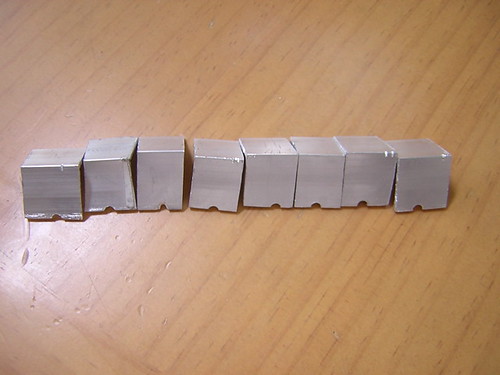
I also did some minimal work related to the utility arms. These are to be held in by a fixed piece of MDF, and a screwed-down piece of aluminum stock. Each of these pieces will have half of a circle cut out of them, supporting the rod that goes though the pivot point in the utility arms. I cut eight pieces of aluminum total, but I really only need four. I figured it couldn't hurt to cut extras, especially since some of them didn't turn out so great.


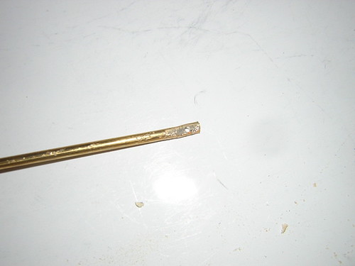
Finally, in order to support the arm swiveling open via a servo, I plan to insert a rod with a hole at the end that will be attached to the servo via a paper clip or something. This rod will go into the pivot end of the arm. I only cut the hole in the rod and cut the rod down to size, I haven't drilled the arms to accommodate this rod yet.

Friday, June 09, 2006

Sanded Horseshoe Shoulder Hub Area, Started Gluing Supports for Utility Arms

The shoulder hubs I received from Jason are just the same size as the area in the horseshoes that they show through (which is good). However,I want to be able to pull the shoulder hubs out without removing the horseshoes, so I sanded the shoulder hub hole in the horseshoe a bit wider, to make removing the shoulder hub easier.

I also glued down the first piece of MDF that will help support the rod going through underside of the bottom utility arm.

Thursday, June 08, 2006

Sanded Booster Cover Putty, Mounted Horseshoes

In the morning, I sanded down the putty that I applied yesterday on the booster covers. The booster covers are in pretty good shape now.

More significantly, in the evening, I mounted the horseshoes onto the legs.

I started by drilling four holes for #8 screws, about 3/4" deep into the inboard side of the horseshoes. The shim layer was taped down in several places on the main portion of the horseshoe.


I then took the shim layer, and taped it down (opposite side up) onto the leg. Lining up the drill bit with the holes that I had just drilled into the shim layer, I drilled matching holes into the outer face of the leg. As each hole was drilled, I placed a #8 screw (head cut off) into the hole, to secure the horseshoe into the leg and keep it from moving.


This came out pretty well. This weekend I'm hoping to cut the hole in the leg for the shoulder hub.

Wednesday, June 07, 2006

Puttied Booster Covers, Started Prepping Horseshoes for Mounting

Today I applied some Plastic Wood wood putty to seams and nicks on the booster covers. I'll sand them down tomorrow.

I also started thinking about mounting the horseshoes onto the legs. They will be held on with four #8 screws on each leg. I'm just planning where the screws will be located. I hope to get to work on these by the weekend.

Tuesday, June 06, 2006

Sanded Curve in Booster Cover Top

When I routed the curve in the booster cover top on Sunday, I used a router bit with a 0.500" radius. The blueprints call for a 0.625" radius (depending on which version of the blueprints you refer to). I taped many layers of masking tape on a pipe with a 0.500" radius, increasing the radius to about 0.625", and started sanding away. A short time later, the curve was to size.

Sunday, June 04, 2006

Lots of Booster Cover Work

After two conspicuous days of no building activity, I finally got back to work on the booster covers. (I was roasting in 100 degree heat at the Dodger game yesterday. I have no good excuse for Friday.) I was determined to finish the remaining major cuts on the booster covers. I literally held my breath during most of them, sometimes due to sawdust.

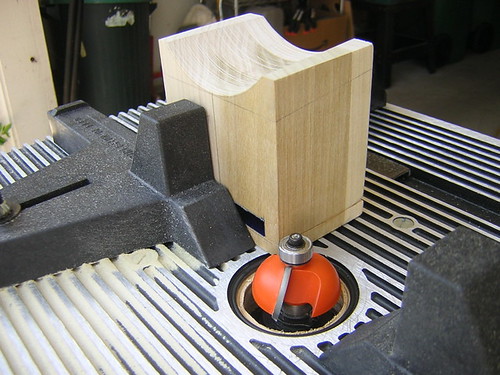
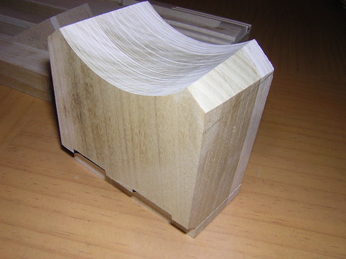
First up, routing out the 90 degree arc from the bottom of the booster covers. I used a cove bit for that.


So far, so good.

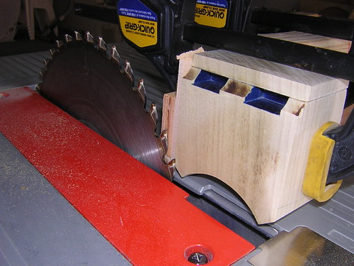
Next, I needed to cut 37 degree angles off the corners of the booster cover tops. This part was really nerve-racking, because we are trying to achieve a very weird shape here when it's all done.


Wow, I can't believe how well that worked!

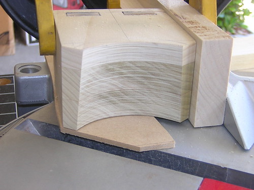
The blueprints call for a three degree angle to be chopped from the front face of the booster cover top (upper part sticks out further than the lower part). So once again I angled the table saw blade, clamped the piece upside down, and ran it through. More success.


The last item of business for the day was routing the grooves in the main part of the booster covers. I set up the fence and stop accordingly, and ran the booster covers through the router four times each (once for each groove).


The little bit of waviness at the bottoms will go away later on, when I chop the bottoms of the booster covers off to open up the "tuning fork." I still need to cut a groove around the main part of the booster covers too, but I'll wait until I know how the booster covers are mounted, so I can match the existing grooves on the legs.

I have to say I am really glad that the trickiest parts of the booster cover build are behind me, and I do feel a small sense of accomplishment having made it this far. A big thank you to all that have helped with booster cover tips and advice (Alan, pixelFiend, Mike and others), your input and encouragement are really appreciated!

Friday, June 02, 2006

Shoulder Hubs Arrive

I didn't get any building done today, but at least I have a little something to report. The shoulder hubs I ordered from Jason Smith's run arrived today. Yea!


I also ordered a set from Pat's run, but a bird in the hand...

Thursday, June 01, 2006

Finished Sanding Utility Arms, Glued & Chopped Booster Cover Tops

In the morning, I finished sanding the utility arms so that they can swing freely open without hitting the skins.

I also was able to remove the masking tape from the booster cover tops, and glue the bottom part of these back on. How did I manage to do such a sloppy job of masking? Huh... oh well.


In the evening I worked up the courage to do some choppin' on the booster cover tops. The blueprints call for a 3 degree angle to be cut off the top. I practiced with the chop saw on a large piece of scrap, and then held my breath and cut the real booster covers.

Phew, it turned out fine.


The angle is pretty subtle, but it is there. Obviously a little wood putty will be in order once I'm done cutting.


I still need to route a curve out of the bottom-front corner, and cut 3 degrees off the front face of the booster cover tops, then the booster cover tops will be pretty much done (except painting and adding mounting screws).