Tuesday, January 30, 2007

Glued Foot Shell Backing Strip, More Aluminum Arrives

Tonight I glued down the backing strips for each of the two foot shells, where the curved part joins the vertical area. This strip of PVC overlaps the two connected pieces, and helps strengthen the overall bond.


The aluminum I ordered from Discount Steel arrived. I didn't unwrap it, as it was apparent that there were a lot of metal shavings in the plastic, and I didn't want to deal with that tonight. But this should help get my drivetrain back in gear (so to speak).

Monday, January 29, 2007

Published Leg Building Tutorial

Tonight I put the finishing touches on my wooden leg building tutorial, and uploaded it.

http://pw2.netcom.com/~artoodetoo/LegTutorial.pdf

This is a 50-page manifesto (more rambling but less dangerous than the Unibomber's), with plenty of pictures to help illustrate each step. It goes well with leg building tutorial on the R2LA III DVD.

Sunday, January 28, 2007

Drilled & Tapped Shaft Adapters

Today I worked on the shaft adapters that will attach to the motors. These are required because the shafts coming out of the motors are only 8mm in diameter, whereas the gears that will drive the chain have a 3/4" inner diameter. I'm using a 1.25" segment of steel rod, per the H&A drivetrain blueprints.

Mike has a handy tool that he let me borrow, that helps to center a hole in the steel rod I'm using for the shaft adapter. The tool has a pre-centered hole on one end, and it lets you place a blank rod in the other. The drill bit slides the through the hole and then drills a centered hole into the blank.


I only need two shaft adapters, one for each motor, but I actually built a total of four just in case. I drilled two with a 17/64" bit, and then went back and drilled two more. (Actually, now that I think about it, I do need a third one for the dome motor.)


Next, I tapped the shaft adapters with an M8 tap, to match the threads on the motors.


The adapters appear to fit the Saturn wiper motors well. I still need to grind some material out around the shaft adapter hole on the motor side, because the shaft adapter needs to fit snugly up against the motor body. Eventually a 1/8" diameter hole for a steel pin will be drilled and the pin inserted, perpendicular to the shaft at its base. This will help lock the shaft adapter to the shaft and prevent shearing, which is prone to happening when running the motors converted from 12 volts to 24 volts, which I plan to do.

Saturday, January 27, 2007

Worked on Vertical Part of Outer Foot Shells

Mike and I were able to put in just a little time on the outer foot shells today.

This time we concentrated on the flat, vertical part of the inboard side of the feet. This is area where the battery boxes rest against the feet. We already cut the curve a few weeks ago from PVC pipe.

First Mike cut some 3.5" sections of 1/8" PVC.


Then he cut a series of small strips to help double the thickness of the PVC, where it will meet the 1/4"-thick pipe segment. We glued those in place.


Finally, we glued the quarter section of PVC pipe to the flat area we just cut. Obviously this all needs to be cut down to size later.


Tomorrow I plan to glue another strip behind the two surfaces where they meet, to help further bond them together.

Friday, January 26, 2007

Finished Sanding Center Foot Shell

Tonight I sanded down the last bit of seam filler on the top portion of the center foot shell. Saturday Mike and I plan to resume work on the remaining cuts for the outer foot shells.

Thursday, January 25, 2007

More Center Foot Shell Cleanup

More of the same from yesterday. Before going to bed last night, I glued down the loose corner of the center foot shell, and used a toothpick to lightly apply some superglue to a seam or two.

Tonight I sanded all that down smooth. I did a tiny bit more filling of the seam where I reglued the corner. Tomorrow I'll sand that smooth, and this part of the foot shell should be set.

The center foot shell is awaiting the glue-up of the bottom "window" strips of PVC, and those strips still need to be cut down to size. That will get done in it's own time.

Wednesday, January 24, 2007

Started Sanding Sides of Center Foot Shell

Looking for anything productive to do during the week, I recalled that the side edges of the partially glued up center foot shell needed sanding.

The original glue-up can be found here.

Tonight I was able to sand most of the edges very smooth. There are some very thin lines that will need to be filled (likely with superglue), and then a final sanding should do it. One corner started to work its way loose, so I avoided sanding that area and I will reglue it.

Saturday, January 20, 2007

Road to Recovery

Okay, I think I'm done pouting (for now, at least). Here's the current plan for the drivetrain, which is spec'd to look as follows:


And here's what one of Mike's looks like, from R2LA III's emergency repair:


First, I'm going to cut out part of the top of the main rectangular tube. That way, the main bar from which the motor mount hangs will be at the specified height, rather than riding on top of or beneath the tube.

Second, I ordered some new aluminum online from Discount Steel. Specifically, I ordered a 4"x6.5"x3/16" thick aluminum bar that perfectly matches the H&A plans. Once I locate it in the proper place, everything will be to spec.

Third, I ordered some aluminum L-bars to ride on top of the main tube, per the H&A plans. It will need to be trimmed a bit, but I've done that before.

Fourth, I haven't totally decided what to do with the bearings since they overshoot the bottom of the tube where I cut it earlier, so I may use a simple flanged bushing, which is also per the H&A spec.

Finally, while I was ordering more aluminum, I decided to order some extra 2"x4"x3/16" rectangular tube, but this time I ordered four shorter segments, which also match the H&A plans.

To summarize, within a week I should have all the main pieces I need to reproduce a replica of the H&A drivetrain, but I may be able to salvage the work I have.

Thursday, January 18, 2007

Drivetrain Woes

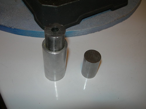
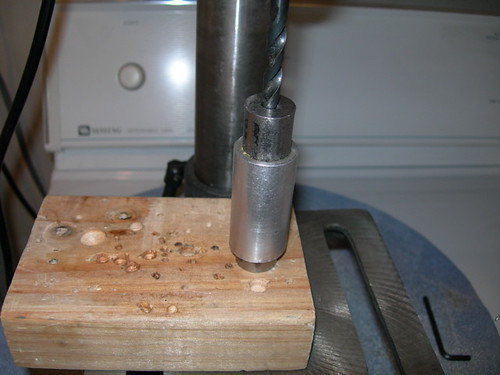
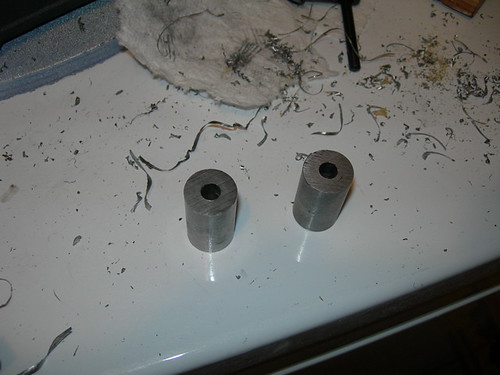
Okay, time to 'fess up. I'm suffering from a severe crisis of confidence in my drivetrain build. I'm moving forward (I purchased more 3/4" diameter steel for axles and shaft adapters today), even as I think I need to retreat. What's the problem? Well, where to start?

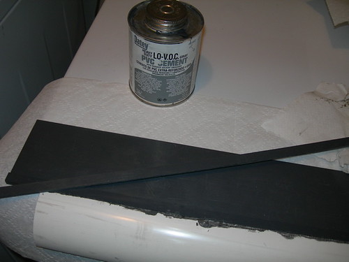
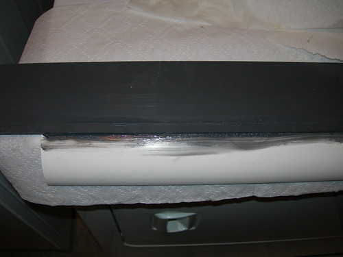
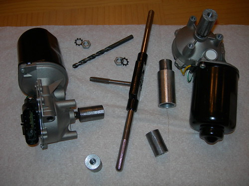
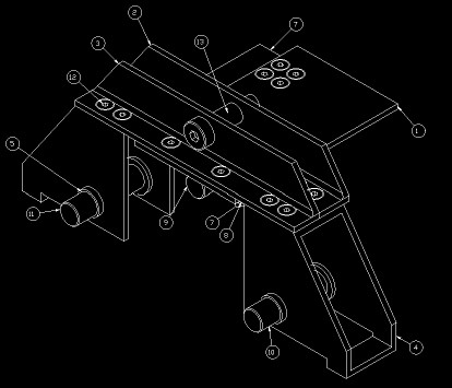
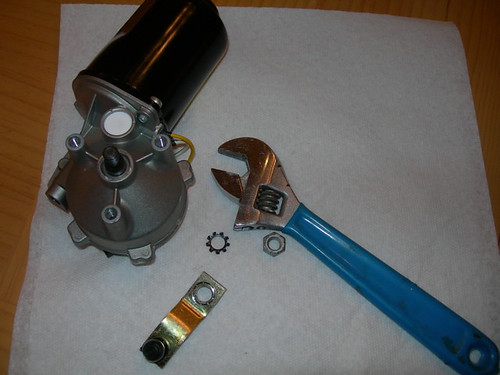
First, I should back up a bit and explain what my approach is. As I've written, I'm working on a modified version of the Heath (MacMillan) & Alex (Kung) drivetrain. I have chosen this drivetrain because it is designed to work with the Saturn windshield wiper motors, and it is a generally nice 2-wheel (per foot) drive. I've chosen the Saturn motors because I like the torque and worm-gear nature of the drive, plus it is relatively inexpensive and readily available. I realize it cannot free-wheel, but I like the fact that the droid won't roll downhill on its own either.

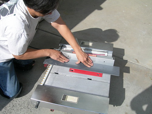
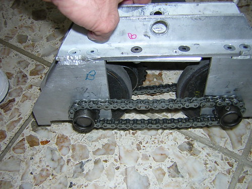
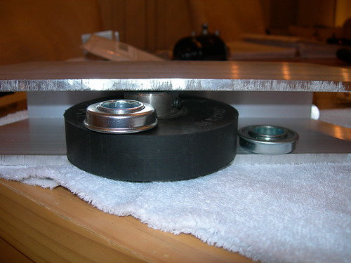
I was planning on using some nice bearings for the axles, but I'm finding that the outer diameter is too large to fit the 2x4. The bottom hangs over the lower cut, where the wheels are exposed to ride on the ground. I can't really raise the bearings, because that will raise the axles, which will raise the wheels, and potentially cause them to run into the inner surface of the 2x4. So I think these bearings are a no-go for this reason alone (but there's more).


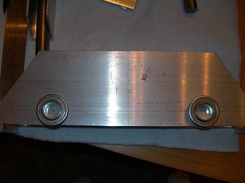
The aluminum 2x4 that I'm using as the main body of the drivetrain has a 1/4" thick wall, while the original H&A design called for a 1/8" thick wall. The bearings won't fit with the standard wheel I'm using, there's no room. In fact, there really isn't much room for a smaller bushing in there either, I'd have to file it down quite a bit.


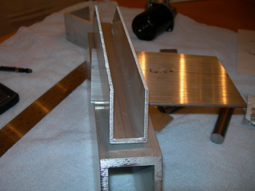
Next problem. The H&A design calls for two "L" channels on top, but I have a single "U" channel. This does a poor job of accommodating the main bar that the motor mount hangs from. Furthermore, this channel must align with the top opening in the foot shell, and I have doubts that this is even possible with the channel I've chosen, though I'm not certain.


There are a boatload of problems beyond the ones I just listed, including (but not limited to):
- I did not cut out most of the siding of the 2x4, so there's no way to slide the main bar under the top of the 2x4 like the H&A plans dictate. The bar would have to ride on top.
- The main bar is 1/16" thinner than specified in the plans (is 1/8" thick, should be 3/16" thick). So far I have not found 3/16" thick stock that is 4" wide. This probably isn't a really big deal, but it means that the measurements for various holes will have to be adjusted by 1/16".
- If I were to proceed with the current approach, lots of other measurements will have to be readjusted. Instead of the motor mount hanging from below the top of the 2x4, it will hang from above it (an additional 1/4" of readjusting measurements). Thus lots of other locations for holes in the motor mount area need to be adjusted correspondingly.

And the list goes on, probably including stuff I haven't even thought about yet.

I'm seriously considering scrapping most of the work I've done so far, and starting over with a 1/8" thick-wall 2x4, with cuts more closely following the H&A design. I need to study all of this some more.

It's really frustrating. Once this and the foot shells are done, the droid is ready for wire-up and motors, and then it will be complete. But I have no idea how long this is going to take. Staring at it nightly and shaking my head doesn't seem to be making it go any faster. This is the 80/20 rule in all its glory.

Maybe if I only stare harder...

Wednesday, January 17, 2007

Measuring & Marking Drivetrain

I spent some time tonight measuring and marking the aluminum tube that will make up the main part of the drivetrain. I will need help from a machine shop to drill the holes for the axles, and maybe more help drilling additional holes.

I started taking measurements on the aluminum, and marked where I believe the axles will go. This is subject to many iterations of remeasuring and remarking.

Tuesday, January 16, 2007

R2LA IV DVD Arrived

Yippee! Michael McMaster's R2LA IV DVD arrived today. Lots of fun-filled material, along with at least two Easter Eggs that I found. This served as the perfect excuse to get nothing done tonight. Not sure what I'll come up with for tomorrow's excuse.


Head on over to http://n2citrus.com/artoo/dvd.html for the fun.

Sunday, January 14, 2007

Resumed PVC Foot Shell Work, Swapped PSI Circuits

After quite a while away from the PVC foot shells, Mike and I got together to resume work on them. Mike did all the stunts, I handled cinematography.


We recut the fronts and backs of the outer foot shells, after discovering a problem with the ones we cut earlier. We also cut the tops of both outer foot shells. The fronts, backs and tops will need to be trimmed to match the actual width of the foot shell. We are waiting until we finish constructing the inboard-side of the foot shell that has the battery box-curve to it, before we trim all of the other sides to size.

The angles on all of these are crazy. Thank goodness we can always take measurements from Mike's first droid.


When I got home, I worked on adding some wiring to my dome for the new PSI flasher circuits.


The diffusion is far from perfect, but I can work on that over time. I do find myself preferring the discrete flash operation to the fade.

Saturday, January 13, 2007

Cut Out Rear Power Coupler Housing

Today I spent all of five minutes cutting out a housing made from wood for the rear power coupler.


This wooden housing will be glued down to the base of the frame. I plan to use Velcro to attach the aluminum power coupler to the housing.

While I could glue the housing down to the frame now, I'm going to wait so as not to impede access to the frame's interior. I figure it would be better to do this after all of the electronics and batteries have been fitted.

Friday, January 12, 2007

Assembled New PSI Circuits

The flasher kits I ordered from allelectronics.com arrived today.

As cool as the fading PSI circuits are, I think I'd like to try having constant, full illumination for each color, so I'm trying these out.


I substituted my own red/blue and green/yellow superbright LEDs for the red ones that come with the kit. So far so good, but I need to play around with the diffusion in the dome a bit before I can declare success.

Thursday, January 11, 2007

Slow Week

Let's see if I can give the appearance of being busy, without really doing anything.

I ordered couple of flasher circuits from allelectronics.com, after seeing them in action in Vince's and Russell's domes at the last two R2LA gatherings. I really like how they looked, so I'm going to experiment with them.

I also played around with my sounds on the CFSound III. Thanks to Mike, I'm able to rotate through a series of many sounds on input #1, and play distinct sounds on the other inputs. I'm manually grounding the inputs to trigger them for now. Once my remote arrives (which is another story...), I can use the remote to trigger them.

Roy Powers stopped by tonight to do some fact finding on the rails, nuts and bolts that help hold parts of R2 together.

Did that give the appearance of being busy? I didn't think so. Mike and I plan to resume work on the PVC foot shells on Sunday, so maybe that will make up for a slow week.

Tuesday, January 09, 2007

Sanded Top of Center Foot Shell (Again)

Well, the JB Weld on the back door from last night seems to be holding, so I put the door back onto the droid.

I sanded down the super glue that I applied to the top of the center foot shell last night. Now the top of the foot shell is nice and flat, with no gaps or pinholes. I still need to sand and smooth down all the sides at some point.

Monday, January 08, 2007

More Back Door, Center Foot Shell Work

If you're ever feeling down, especially if you've just messed something up, or can't get something to work right, console yourself. You aren't as bad as I am.

How many times have I destroyed and repaired various parts of my back door now? I've lost count. Anyway, one of my new coin returns worked loose, so I did the JB Weld thing again. It's starting to look like Frankenstein back there.


The center foot shell was feeling neglected, so I filled in some remaining pinholes in the PVC with some super glue. I'll give that a final sanding (at least it should be final) tomorrow. With any luck, Mike and I will resume work on the foot shells soon.


I'm surprised I didn't glue the bottle to the foot shell.

Sunday, January 07, 2007

R2LA IV.5 - Leg Finishing

Today was Mike Senna's leg-finishing session for the local R2 builders that purchased Matthew Henricks' wooden legs. It was also an excuse for others of us to just get together and have a good time.


Mike went over how to apply Bondo and/or Evercoat to even out the legs.


After applying the putty, Mike sanded the surface smooth.


Other details were covered, such as filling in the pockets for the under shoulder details.

But best of all, it gave me an opportunity to put on a Stormtrooper helmet. The benefits of this club never end.


Everyone went home happy, and a good time was had by all.

Saturday, January 06, 2007

One More Band Saw Cut for Drivetrain, Attached New Rear Coin Returns

One last, penultimate cut on the band saw for the drivetrain. I had bought too little aluminum 1/8"x4" stock, so I picked up some more earlier in the week, and finally went to Kelvin's to have it cut today.


In the afternoon, I JB Welded Wayne's aluminum coin returns into the back door. I will work on the front coin return in the not-too-distant future.

Friday, January 05, 2007

Coin Returns Arrive

The coin returns from Wayne's run arrived today, and they look great.


I'm almost certainly going to use these on my droid, since my scratch-built coin returns are less than spectacular.

This culminates a pretty passive work week. I didn't really get any building done, hopefully I'll be more productive soon.

I'm also working on a wooden leg building tutorial, which I hope to finish soon.

Wednesday, January 03, 2007

Motor Homework

I can't claim I did much in the way of building tonight, but since I'm working on the drivetrain, I figured I better start studying up on the Saturn wiper motors I'm planning to use. I removed the bar that controls the windshield wipers.


Then I read up on how the connections to the motor work, and I reviewed Alex Kung's summary on 24 volt conversion, which I plan to implement.

Tuesday, January 02, 2007

Glued on Rear Power Coupler Frame

Tonight I used silicone to attach the rear power coupler frame to the inside of the back door. (You'll recall I knocked out the two rear coin returns when I was bending the door to fit the body, I'll deal with those a bit later.)


I'm not 100% convinced that the silicone will hold for the long term, but I'm giving it a try. If it doesn't hold, I'll try again with JB Weld.