Wednesday, December 31, 2008

Drivetrain Build Completed

At long last, after one more visit to Mike's, my new drivetrains are done (or 99% done). We shot some video that supplements the R2LA VI DVD drivetrain tutorial, it can be fount here:

Part 1
Part 2

I used the Dremel cutoff wheel to trim the motor mount bolts to size to avoid having them interfere with the chain, and I needed to cut down the bolts that secure the motor to the motor mount as well.


Next, I took the plunge and drilled out the 1/2" ankle bolt holes for the channel pieces.


The ankle bolt holes will house a 1/2"->3/8" bushings, and these bushings need to be ground down a bit, as they are longer than the channels' wall thickness.


The drivetrains are pretty much done, other than having the bushings pressed in, and having the channels painted white.


Now comes the inevitable fight to get the motors to fit into the battery boxes. Also, these motors only run on 12 volts, whereas my droid currently supplies 24 volts to the motors, so my power needs to be adjusted. As I'm running out of vacation time, I'm not sure how soon I'll get to those tasks.

Tuesday, December 30, 2008

Drivetrains Nearing Completion

The finish line is near (or in Mike's case, behind him). Today was another long day working on the drivetrains, but things are coming to a close.

I started off by hacking through a total of six inches worth of steel axles.


Meanwhile, Mike was busy figuring out precisely where to locate each motor mount piece. This is crucial to the success of the drivetrain. We plan to shoot some addition video on this tomorrow, to supplement the drivetrain tutorial on the R2LA VI DVD. We'll probably upload it to YouTube.


Once the motor mount locations were determined, they were marked and each of us drilled ours.


Each of us trimmed the motor mount overhang on the band saw.


I worked on the chain for the drive side of each drivetrain. When it came to tensioning the chain, we decided to shim the motor away from the motor mount and closer to the gear on the wheel axle, rather than attempt to mill slots with a non-existent mill. This was a time-consuming, iterative process. Both of my motor mounts have a 1/32" shim layer between the motor mount and the motor, which provides a little slack in the chain.


Mike drilled the ankle bolt holes in his top channel. I wasn't ready to drill the ankle bolt holes just yet, as I needed to measure the holes on the existing H&A drivetrains, and have the new holes match.


By the end of the evening, Mike had his drivetrains fitting perfectly inside his foot shells. All he needs to do is trim the bottom of the battery boxes slightly, and he will be completely done. I still need to cut some bolts down to size, and have the ankle bolt holes drilled, along with needing to trim some of the bottom of the battery boxes. Getting close!

Monday, December 29, 2008

Drivetrain Channel and Motor Mount Work

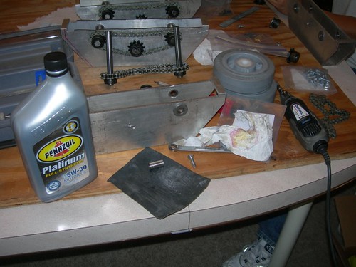
Back to work on the drivetrains. As we get closer to the finish, we must proceed even more carefully. This is particularly true when working on the motor mounts, as space is very tight, and a mistaken measurement or drilled hole can mean quite a setback.

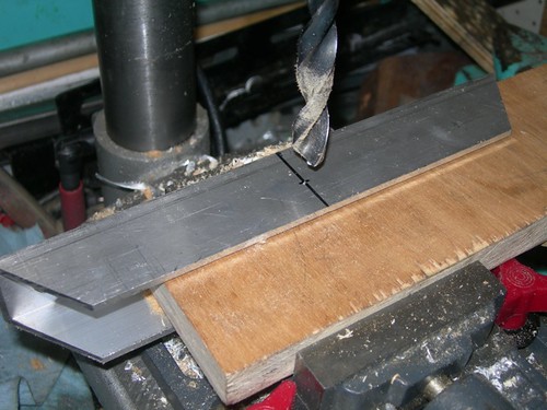
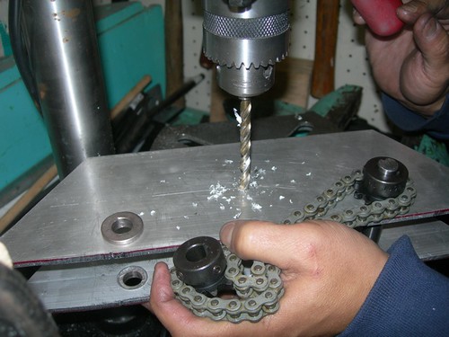
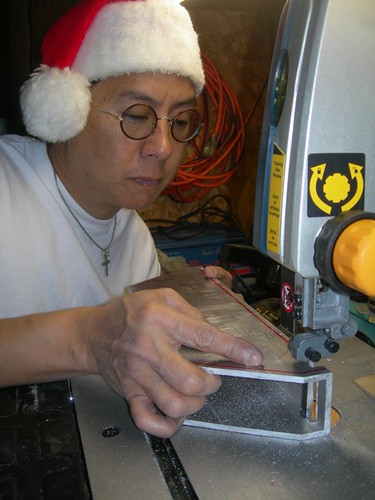
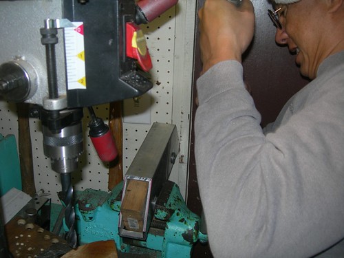
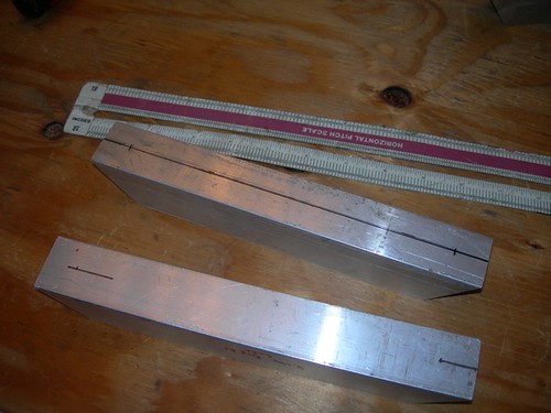
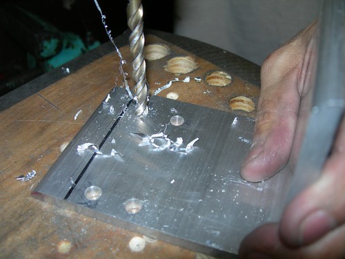
We started with marking and drilling the channel pieces that go on top of the drivetrain.


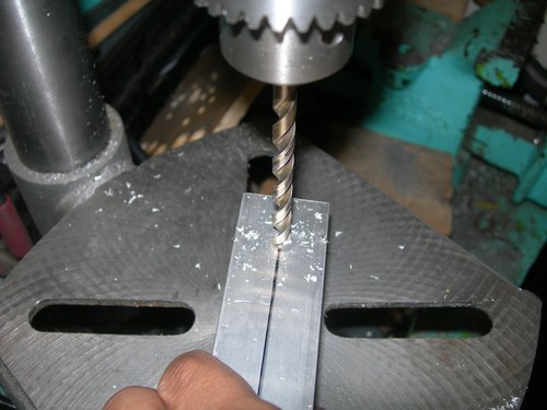
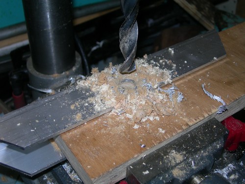
Once the channel pieces had their holes drilled, they were used as templates to drill the holes into the tops of the drivetrain body pieces.


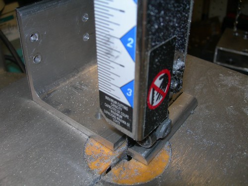
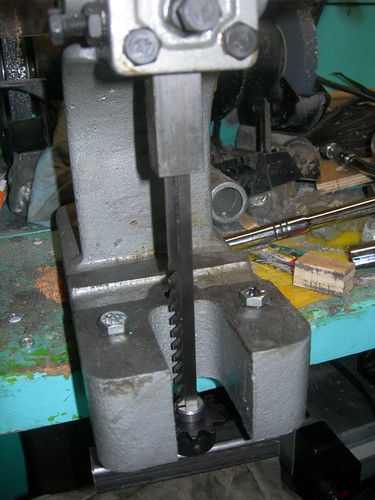
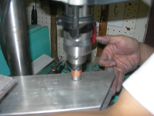
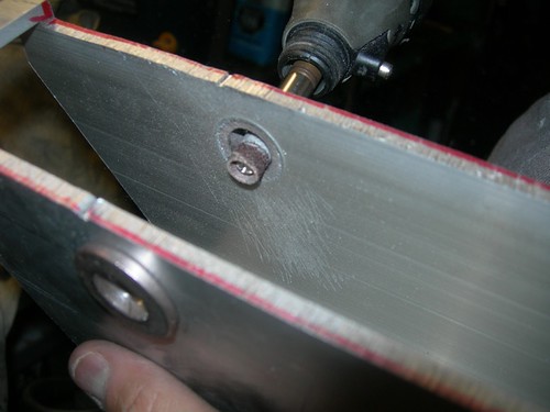
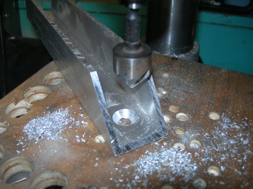
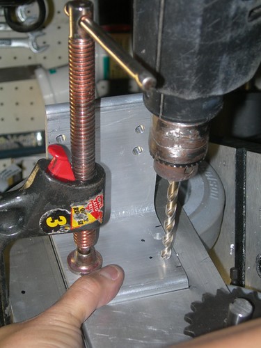
After those holes were drilled, we returned to the drill press to countersink the holes in the channels.


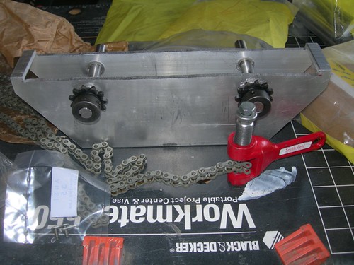
Next, it was time to move onto one of the trickiest parts of the build, the motor mounts. These segments of L bracket need to be located just right, both vertically and horizontally. We want to locate them as low as possible, to give the NPC motors as much room up top as possible in the battery boxes. In the horizontal direction, we must be mindful not to block access to the ankle bolts when the motor is installed, and yet leave as much distance as possible for the chain to span the gear on the motor and the corresponding gear on the drivetrain.

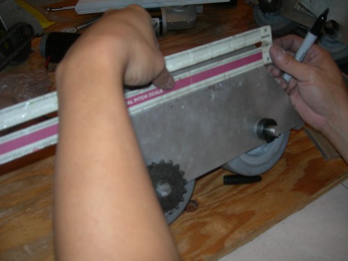
Mike spent quite a bit of time determining where best to locate the motor mount on the drivetrain.


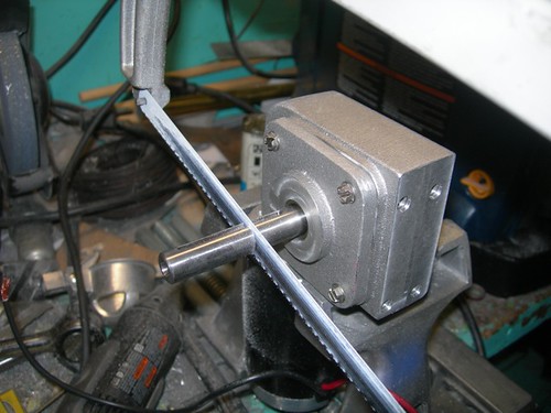
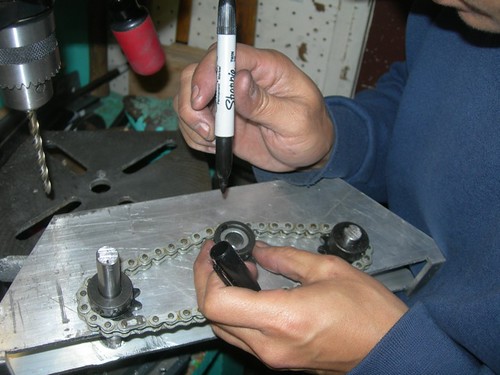
Once the location was determined, he used a piece of paper as a template to match the hole locations on the NPC motors.


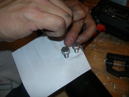
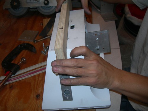
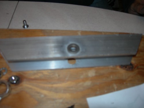
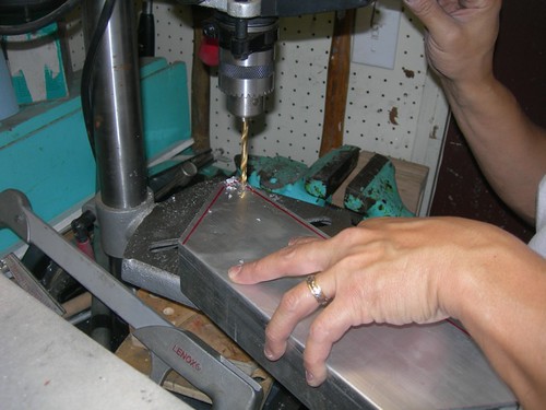
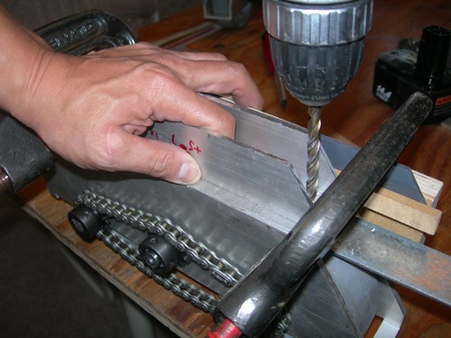
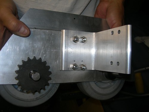
Mike transferred the paper template to the motor mount piece, and used it to mark up the piece for drilling.


Perfect on the first try, all four holes that were drilled lined up with the four holes on the NPC motors.


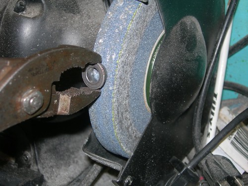
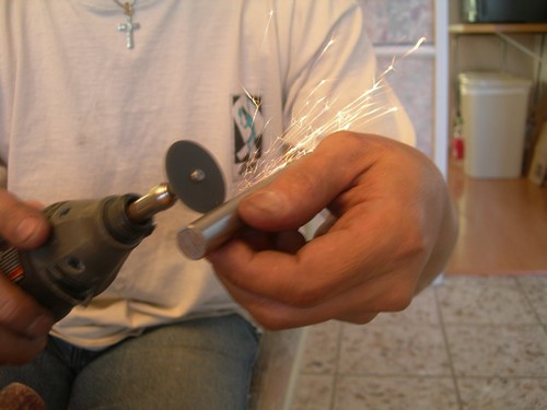
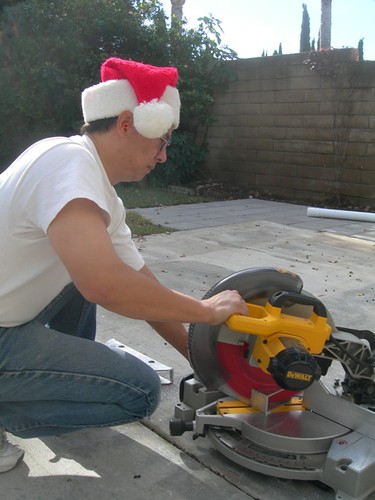
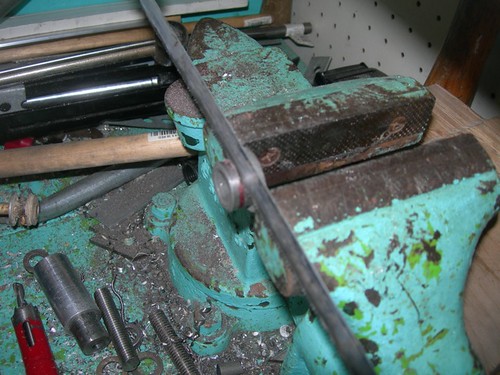
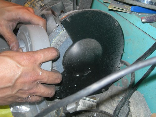
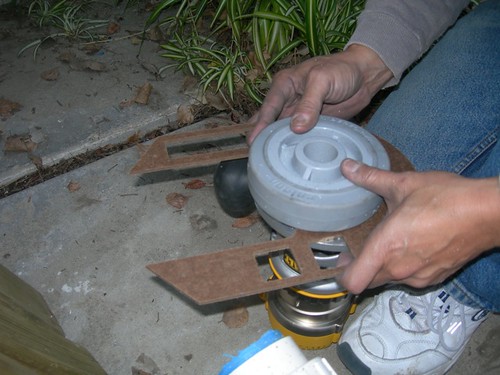
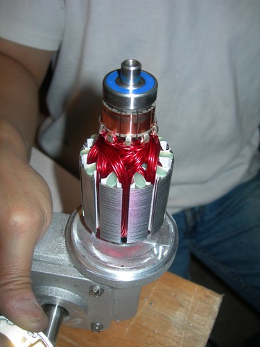
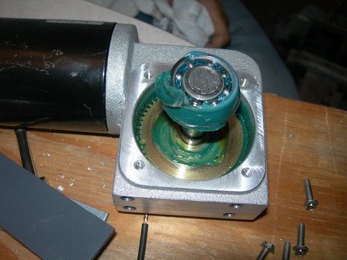
Speaking of the NPC motors, we came to the realization that the tops would need to be ground down somewhat, to accommodate the curve at the top of the battery boxes. Before grinding, we wanted to make sure we knew what we were grinding into, so Mike took the cover off the NPC motor. (By the way, don't do this yourself unless you want to struggle with getting springs and commutators back into position, which is quite a pain.)


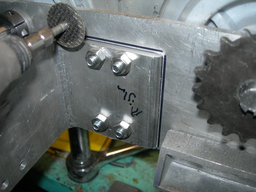
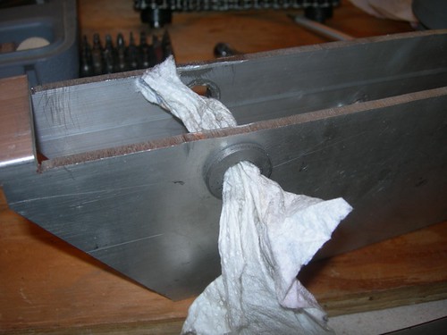
Next, the holes for mounting the motor mount onto the drivetrain were drilled.


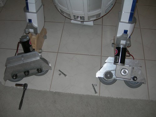
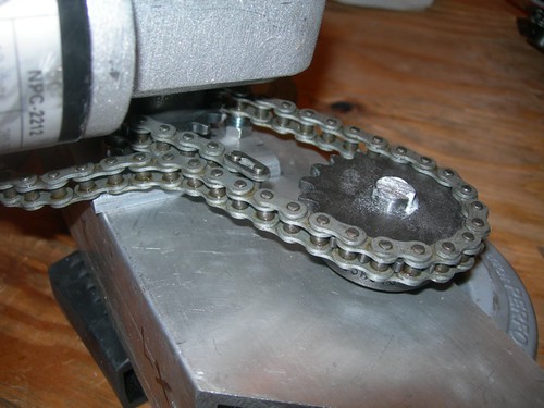
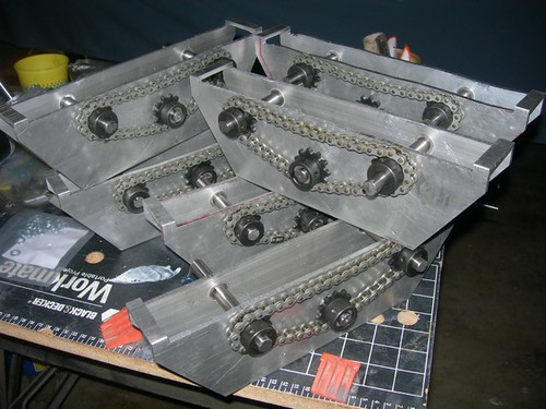
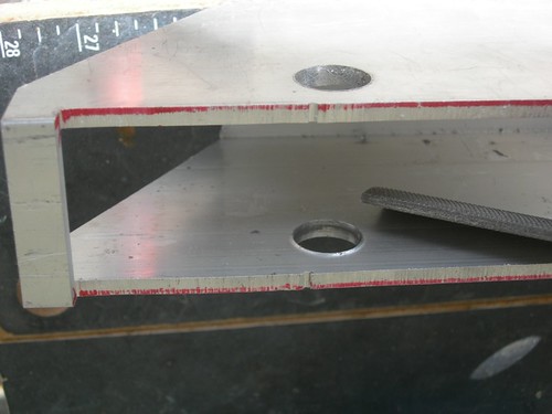
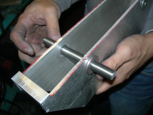
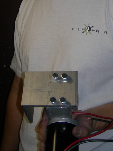
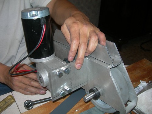
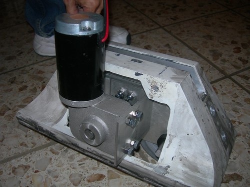
Now the motor mount is attached to the drivetrain.


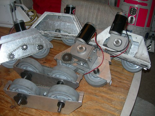
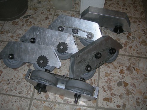
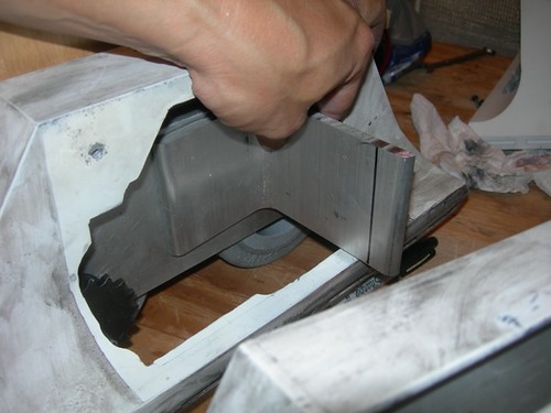
Here is the drivetrain in its current state, very close to being done.


It fits well in the foot shell, the battery boxes will need some (hopefully) light trimming.


Of the original six drivetrains, two of my four will be put on hold because I still need to build my A&A foot shells before proceeding. We went very slowly and carefully on today's drivetrain, we are hopeful the other three will go more quickly. Beside what we did today, we still need to build up the drive-side chain, mill out some space to tension the chain on the drive side, and drill the ankle bolt holes.

Sunday, December 28, 2008

Final Drivetrain Assembly Started

Back to work on the drivetrains!


Yesterday we did some cutting and fitting and some rough assembly. Today we started doing final assembly on some of the parts of the drivetrain. Final assembly includes fun activities such as lightly sanding and lubricating shafts, Dremeling out and cleaning flanges, and sanding key stock.


Sparks! Mike is not cutting the keyway here, he's just clearing some debris that was stuck in the keyway in the axle.


Here is the mysterious keyway in action. A slot is cut into both the axle and the gear. A segment of 1/8" square rod is placed into the slot on the axle, and the gear slides over it, locking the gear to the axle. This way, the gear won't ever slip. Set screws on the gear also help hold the gear onto the axle.


Likewise, the Delrin ring inside the wheel hub also has a keyway cut into it, and this locks the wheel onto the axle as well. A washer is located on each side of the wheel, inside the drivetrain body. The washers virtually eliminate friction as the wheel turns inside the drivetrain.


This looks a lot like yesterday, but yesterday was mainly prep for today. Today we now have the keys in the keyways, the wheels and washers installed, and the large gear mounted.


The motor mounts are probably the next item of business. These will be tricky, because we need to get everything to fit into our existing foot shells and battery boxes.

Saturday, December 27, 2008

Drivetrain Assembly Work

The march of progress continues... Today Mike and I picked up where we left off on the drivetrains.

Mike cut the keyways on the many gears that had not yet had them cut. These keyways will allow a square piece of aluminum stock to lock the gears to the axles, as we'll see a little later in the build. A press is used to drive the keyway cutter into the gear. Each tooth on the cutter shaves off a small amount of material.


Meanwhile, I worked on the chain, cutting and linking it together to the proper length (eventually).


After building the chain, I cut 1" off the ends of the NPC shafts, so that these short pieces could be used to hold the tensioning gear.


Mike measured, marked and drilled the locations where the tensioning gear should be located on each drivetrain body.


Several hours later, one side of the six drivetrains is nearing completion.


The drivetrains are getting there. We still need to attach the motor mount brackets and build the chain for the motor side, and attach the top channel that we cut earlier.

Sunday, December 21, 2008

Drivetrain Work Resumes

A very busy day at Mike's today, working on lots of details for the drivetrains.

The first order of business was to cut a piece of aluminum tube that I had ordered, to match the five other tubes we had already cut. This tube replaces the sixth one we cut during the tutorial DVD shoot, as that one had one of the axle holes drilled slightly out of alignment.

Ho ho ho!


Mike drilled a series of overlapping adjacent holes to allow the band saw blade enough room to get into a slot for cutting the bottom wheel area out.


While Mike was busy with the aluminum tube, I kept busy cutting many, many bushings down to size. There are 3 droids x 2 feet per droid x 4 bushings per foot = 24 bushings to cut down. Mike had already cut several of these before I arrived, but there were plenty left to cut.


Once Mike was done cutting the tube, he drilled the holes for the axels.


The hole saw leaves a small ridge on the inside of the tube, so I filed all of these down smooth.


Mike pressed the bushings in with a vise. A block of wood is inserted in the tube to prevent the tube from caving in as the vise squeezes the bushings in.


Pressing the bushings in can narrow the inner diameter very slightly. Running a 1/2" drill bit through them and polishing the inside with a small Dremel drum sander widens them just right.


The wheels we are using are just slightly too wide to fit in the aluminum tube. Mike and I tried using the bench grinder to slim them down, but we found the rubber was melting into the grinding wheel.


Mike got the idea of using his router with the bit set low, and ran the wheel along the tip of the router bit to shave down the high areas. A horseshoe acts as a router plate. That worked quite well, actually.


Mike and I cut the Delrin rings down to size with the band saw. These go in the wheel and have a keyway cut into them, as do the axels that go inside the Delrin rings.


The last item of business for the day was to insert the Delrin rings into the wheels.


That's it for now. The next time we get together we'll cut the keyways into the gears. After that, it's on to the chain and tensioning gear, and some holes for the motor mounts and channels need to be drilled.