Thursday, March 31, 2011

Painted Battery Box Doors, Side Skin Panels

It was such a warm day here today (high 80s/low 90s) that I had to take a short break from the electronics and paint something.

I looked around for something ready to go, and went with the simplest things I could find: The battery box doors, and the small square pieces of styrene that cover the gaps at the bottom of each side of the skins. On droid #1, I didn't even paint these side pieces since they were originally already white, but I should have, as the styrene and white paint fade differently.

All these panels had already been primed and sanded smooth.


I applied three coats of Rustoleum Satin White paint, about ten minutes apart.


Hopefully that'll do. I'll look them over tomorrow and check to see if they could use another coat or two, but I think they may be good to go.

Tuesday, March 29, 2011

Attached CFSound III to Panel, Platform for Fuse Box, Attached Connector to Motor

Tonight I did a little more work on the electronics.

Earlier, I had used the bottom cover of the CFSound III board as a template for where to drill the mounting holes.


Tonight I went to OSH to pick up some 1.25" #4 wood screws that are long enough to span from behind the wooden panel, and on into the case. The original screws were 3/4", but between the plywood and rubber feet, I needed the extra 1/2". I screwed in the screws from the back side of the panel.


The screws now hold the CFSound III onto the panel.


Next, I mounted the fuse box onto a small block of particle board.


I plan to attach this to the wooden electronics panel such that the fuses face straight up. If I had attached the fuse box straight to the panel, they would have been facing toward the front of the droid.


The last item of business for the evening was to attach the connectors that I plan to use for the motor. I clipped off the factory connectors.


I soldered on the connector.


I wrapped the solder joints with electrical tape and shrink tubing.


I hope to keep getting a bit more done each day.

Monday, March 28, 2011

Prepped Fuse Box, Attached Dome Controller and Circuit to Panel

Tonight I did a little work on the electronics panel.

I'm going to use a fuse box to distribute power to the various components. Copying Mike's example, I bent the tabs on one side of the fuse box so that when the tabs are soldered together, one single positive wire from the 12 volt battery supplies the fuse box with power, and each individual 12 volt component will attach to one tab on the other side of the fuse box. The negative battery connection will attach to a bolt that the negative connection of all other components will also attach to. These will replace the positive and negative bus bars that I have on droid #1.


Next, I soldered the tabs together. It looks ugly, but according to the continuity tester, the thing does conduct electricity from end to end. (Why do I have a feeling that when Mike sees this in person, he will be compelled to re-solder it?)


In preparation for attaching the dome controller to the panel, I needed to drill holes though the PVC sheet that hosts the components, since the PVC will ride above the panel.


I screwed down the dome controller and circuit, and attached the 1/4" bolt that will act as the negative bus bar. I've also started laying out where I want to place the other various components. The CFSound III is definitely going at the top-center, with the card facing up (obviously). I haven't decided how I want to mount the fuse box yet. I will probably do what Mike did, and have the fuses face straight up. I also need to not forget to add a slightly lower current circuit breaker ahead of the fuse box, so that it will trip first.

Sunday, March 27, 2011

Finished Dome and Sound Automation Circuit Wiring, Worked on Dome Controller Wiring

Tonight I started working on some of the components that will live on the electronics panel. I started with the dome and sound automation controller, and the dome controller, from the tutorials I've referenced earlier.

The dome and sound automation controller has a switch that enables or disables the circuit. The switch is of the DPDT variety, and five of the six connections are used. The signals are carried from the circuit to the switch via a category 5 Ethernet cable. Now is the time to chop off the connector end of the cable.


Next, I soldered the five of eight wires to their respective contacts on the switch.


I did a quick test of the circuit's servo-centering abilities, and they worked as expected.

I then started wiring up the snap switches on the dome controller. The Normally Closed contacts are connected with a black wire. I did my usual sloppy job of soldering, but the connection seems to be holding okay.


The red wire connects the Normally Open contacts.


The controller gets its power from the main 12 volt battery. I soldered the wires that will be connected to the power bus to one of the two snap switches. That's all that's required for power.


Finally, I loosely attached the motor wires to the Common connection.


Time to try it out with the 12 volt battery attached! When the servo is in the neutral position, the motor should not move. When either snap switch is actuated, the motor should turn in one direction or the other. I tested the circuit by manually moving the servo disc, but soon I will have the dome and sound automation controller turn it automatically.


I hope to continue the wire up throughout the week.

Saturday, March 26, 2011

Cut Out and Hacked Frame for Electronics Panel

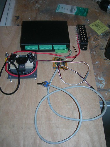
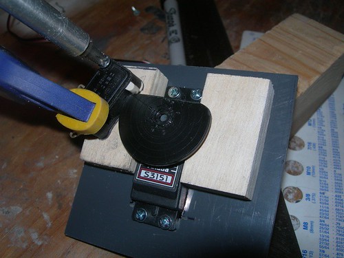
I had been stalled most of the week because I wanted to work on the electronics inside the droid, but I wanted to use an electronics panel, rather than attach the electronics to the frame, as I did on droid #1.

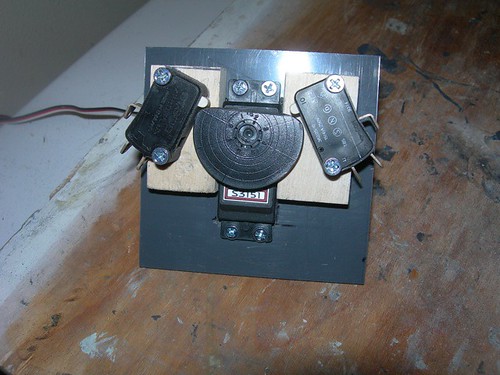
The electronics panel will be made from 1/4" plywood. Mike Senna did a nice job of this, as seen in 
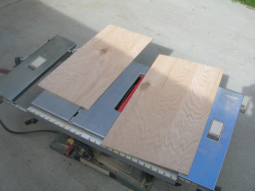
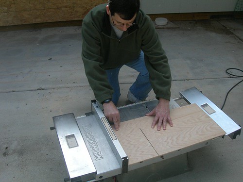
this photoset. I went over to Mike's to use his table saw to cut the panel, and to ask questions about the wiring.

The first step is to figure out where the electronics panel should go. In Mike's example, it went just in front of the center leg. I neglected to bring the center leg, but fortunately this blog entry showed a picture of where the leg and vertical bar meet. Luckily, I did bring the vertical bar, so we used that as a guide.

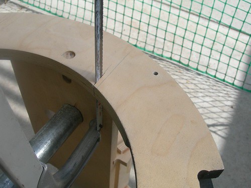
We dropped a piece of plywood flush against the vertical rail, and used another piece of MDF to mark where the back of the electronics panel should sit.


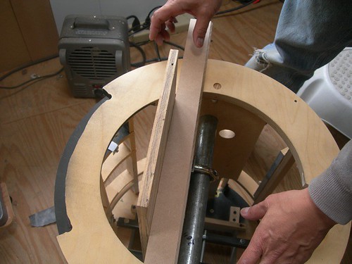
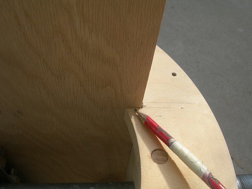
I rested the panel on top of the frame, aligned the back side with the first mark that was just made, and marked where the front of the panel hit the top of the frame.


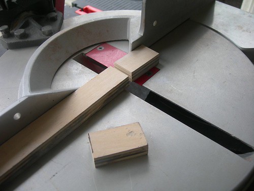
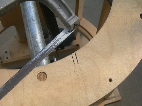
I used hacksaw to start carving out the notches.


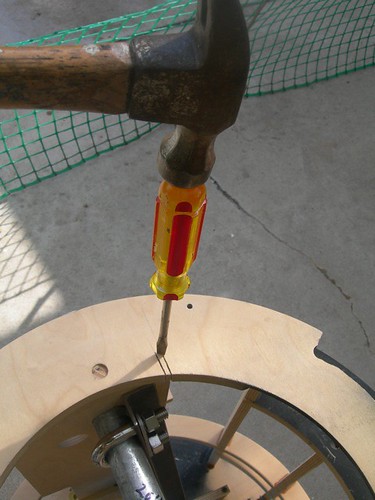
I used a hammer and screwdriver as a poor man's chisel to knock out the notch once the ends had been cut.


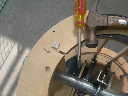
A file helped clean things up.


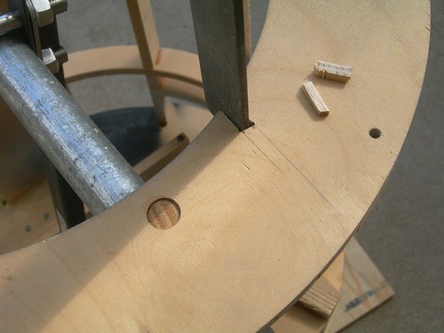
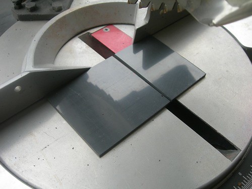
I marked the width of the cut on the frame onto the panel, in preparation for the first cut.


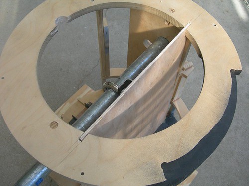
I used Mike's table saw to cut the panel to the proper width.


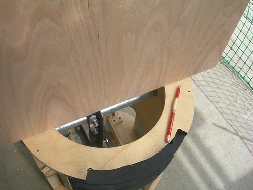
I slid the panel into the frame, and marked the proper height.


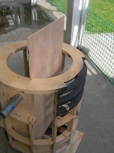
I put Mike to work briefly as the photographer, and cut the panel to the proper height.


The fit in the frame looks pretty good.


When I got home, I temporarily installed the center leg, and found that while the panel does fit, it's a tight squeeze. I might file the slots in the frame so that the bottom of the panel slopes forward a bit more, or I may slightly trim a portion of the top of the center leg that lives high inside the body. We'll see.

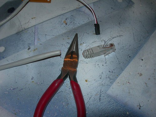
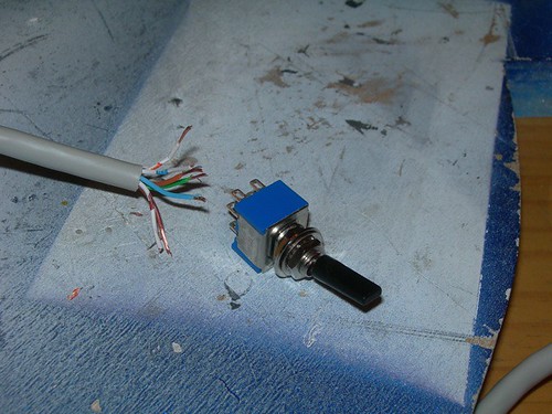
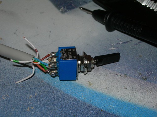
Soon I'll start installing the electronics on the panel, on the way to having sound and dome rotation working.

Sunday, March 20, 2011

Started Dome Controller

Today I got started on the dome drive controller. This is the same controller that I have in droid #1, as designed by Mike Senna and documented by Mike and me in this tutorial.

First, I cut a couple of blocks of wood that will hold the snap switches that I'll be using to control dome rotation.


Next, I measured and cut a scrap piece of PVC that will hold all the parts to the dome controller.


Then, I marked the perimeter of the servo that makes contact with the snap switches.


I cut the rectangle out with the Dremel cutoff wheel attachment.


The fit looks good.


I drilled mounting holes for the four #4 1/2" wood screws that I'm using to attach the servo to the PVC.


Next, I drilled pilot holes into the wooden blocks from behind for the same #4 1/2" wood screws that I'm using to attach the blocks from behind to the PVC.


I screwed the blocks down from behind with the wood screws.


I then fit the larger servo disc in place, and did a test fitting of the snap switches to see where they should be placed, and to see where I needed to cut the disc.


I again used the Dremel with the cutoff wheel attachment to cut part of the disc away.


I used a file to round the corners.


I found that while the wooden blocks were workable at their original positions, the overall fit of the snap switches would be better if I adjusted the blocks to be a bit higher on the PVC, so I did. I then clamped the left snap switch in place, and used a #4 3/4" wood screw to attach the switch in place to the wooden block.


I did the same for the right switch. With both switches in place, and the disc in the neutral position, neither switch is actuated.


When the servo pivots clockwise, the left switch is pressed. When the wiring is complete, this will cause the dome to rotate clockwise.


Likewise, when the servo pivots counterclockwise, so rotates the dome.


I will attach this to the dome and sound automation circuit later, as I finish the electronics build-out of this droid.