Monday, April 30, 2007

Right Motor Troubles, Glued Down Door Holders

When I powered R2 back up tonight, his right motor was not moving. After some troubleshooting, I determined the problem was with the motor itself. I removed the motor and applied 12 volts to it. As I rotated the motor case around in my hand, the motor would occasionally engage. That made my 24 volt conversion inside the motor my primary suspect.

I opened up the motor, and it seemed as though the solder joint was somewhat loose, so I resoldered it. A few minutes later when I reapplied power, I saw a tiny spark from under the motor's circuit board, and the motor was history. I don't know why that happened. I'm slowly frying my droid, one part at a time.

The big bummer of all this is not so much that the motor is trashed, but that it meant all the work I did on the shaft adapter was wasted, since the shaft adapter is JB Welded to the motor shaft. So I had to grab another shaft adapter, open up the base to fit the profile of the motor shaft, and JB Weld it onto a new motor. I'll pin it tomorrow, after the JB Weld has dried. (Hmm... maybe I should have tried 24 volts before JB Welding the shaft adapter onto the shaft, eh?)


I also finally got around to gluing down the new bottom door holders on the outer foot shell doors. I'll nail in the pivot pieces tomorrow, and then the foot shells should be ready for a reprime and paint, although I still need to drill some small holes through the top of the outer foot shells, to allow the wires to pass from the legs on into the feet.

Sunday, April 29, 2007

Second Steps

A little more of the same from yesterday, but that's a good thing.

I went back to Mike's to pick up R2 and bring him home. While I was there, Mike kindly wired up my batteries so they can be easily connected to the inside of R2's power bus, and he also wired up my battery chargers to hook up to the batteries. In addition, Mike installed the main circuit breaker, which should trip before the fuses on each battery pack ever get hit.

A short video of R2's second day of locomotion is available at:

http://pw2.netcom.com/~artoodetoo/R2sFirstSteps.html

Mike piloted the controls for that small shot, he knows what he's doing. In the few minutes that I've had the stick, I've proceeded very cautiously.

(If you can't hear what was said toward end of the video and are wondering what we discussed, Mike asked if I had tightened down the bolts on the drivetrain. I replied, "Not really... not with a wrench. The feet may fall off in the middle of this.")

I brought R2 home, and later in the evening I put him back together. I'm charging up the batteries for about 20 hours before running R2 again.

I also spent all of five minutes recutting bottom door holders, I'll glue them on soon.

Saturday, April 28, 2007

First Steps

R2 took his first steps today. Here's the tale of how the day went.

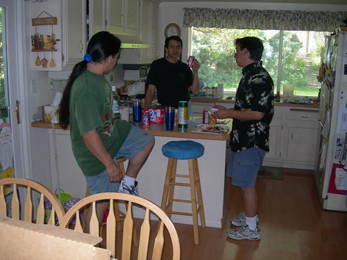
I got to Mike's around 10:00am, William Miyamoto joined us a short time later, and Roy Powers also dropped by for a while and lent a hand. My main function was to stay out of the way as much as possible and operate the video camera, as we were shooting the wire-up for a DVD tutorial.

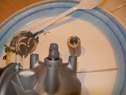
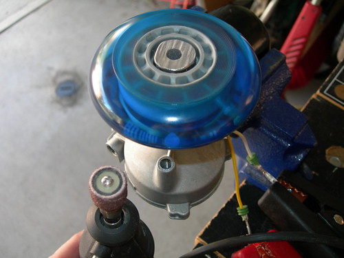
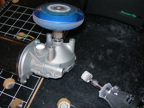
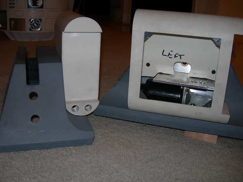
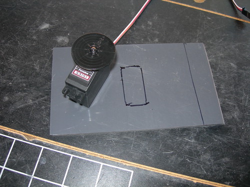
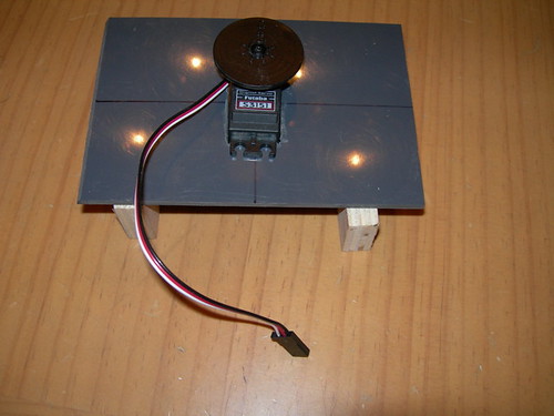
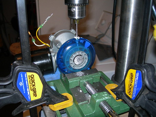
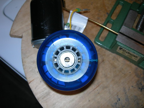
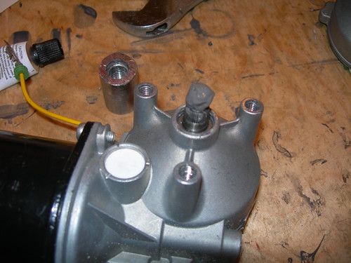
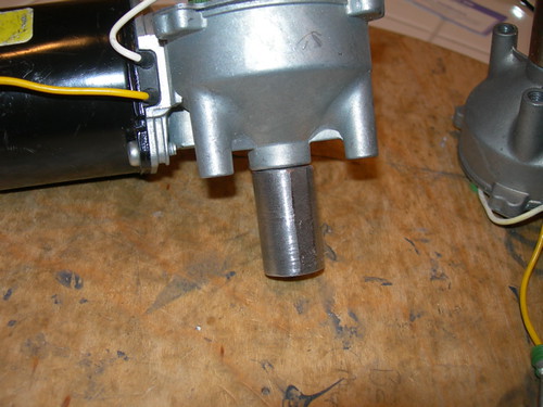
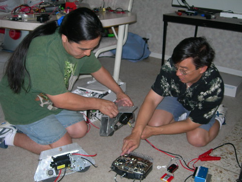
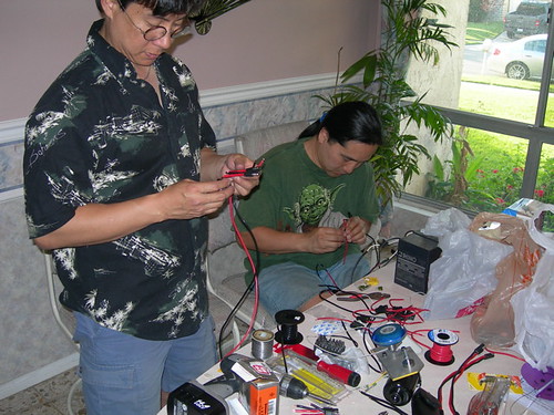
Mike and William worked on wiring up the Saturn motors.


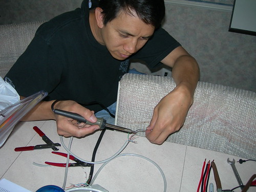
Meanwhile, Roy tinned up some of the data lines for the sound card.


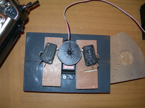
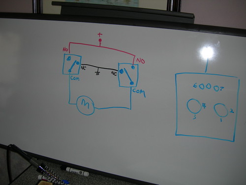
Part of the DVD tutorial included some whiteboard explanation. Mike explained radio control basics, and later diagrammed how the dome motor controller worked.


We had a late lunch break (around 2:30pm) and wolfed down pizza before returning to work.


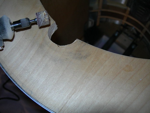
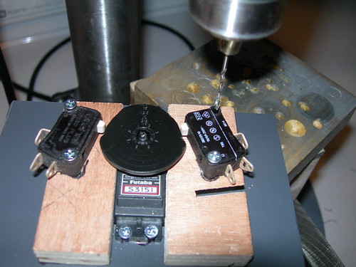
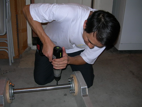
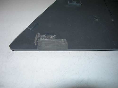
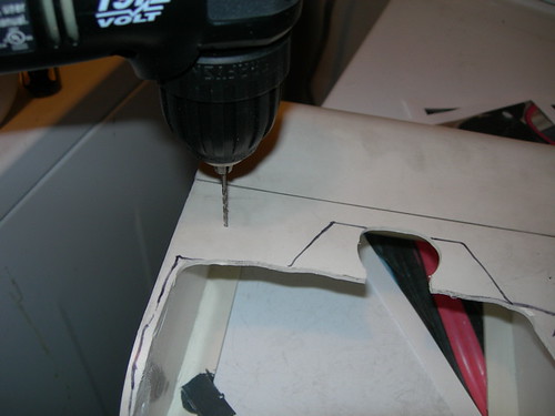
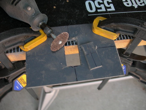
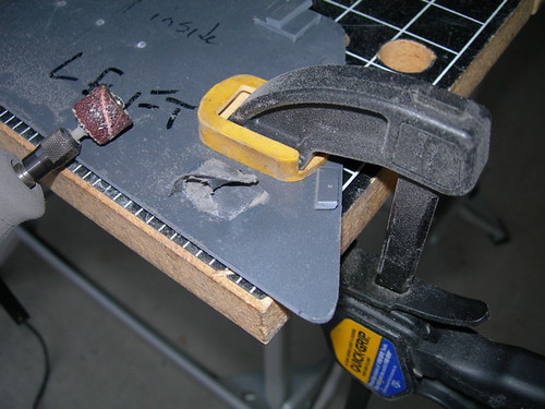
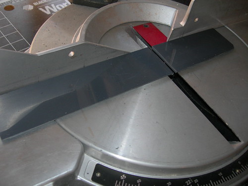
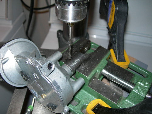
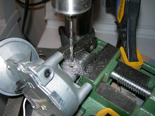
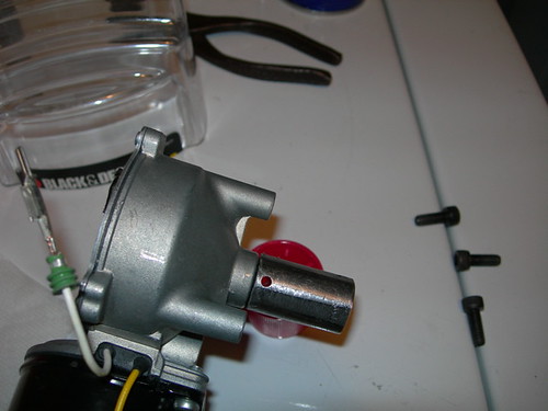
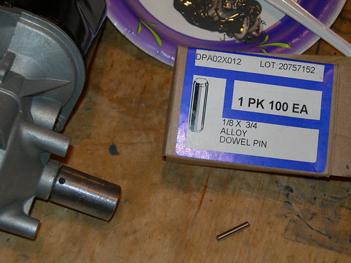
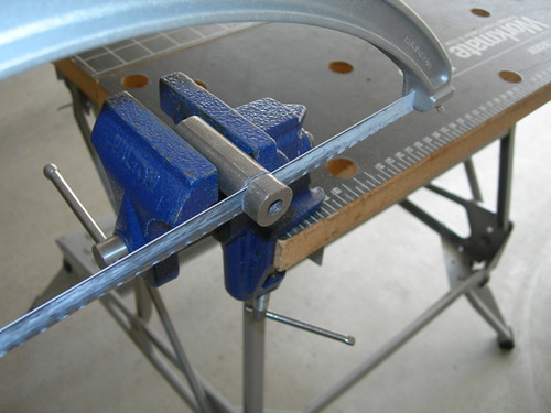
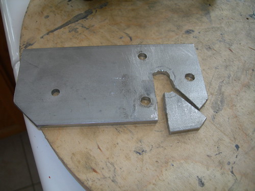
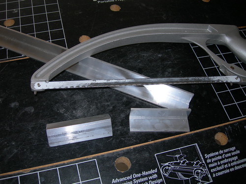
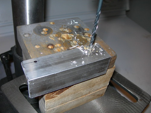
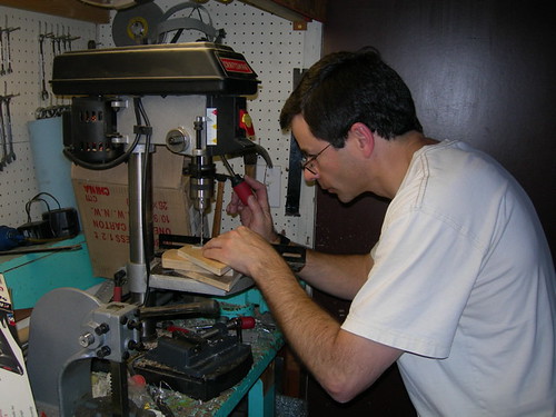
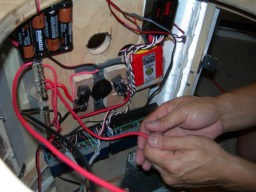
I got into the act every once in a while, mostly hacking aluminum and drilling pieces here and there. I also wired up the data lines for the sound card, and there are a lot of connections to make (32 total, 16 on the Vantec Keycoder, and 16 on the sound card).


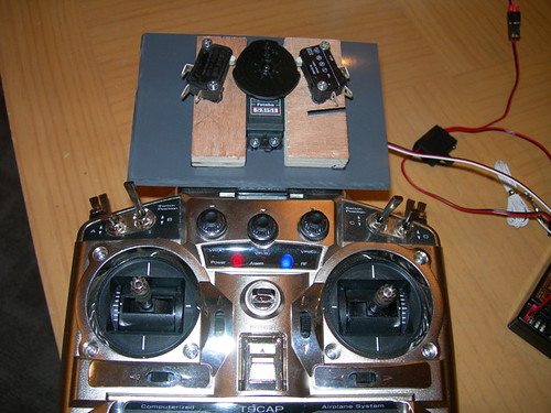
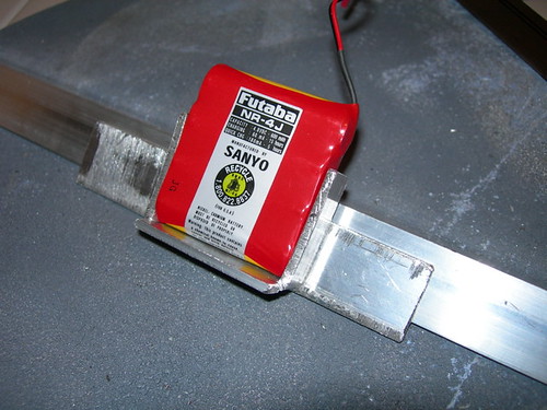
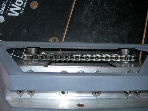
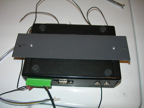
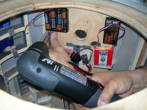
Mike added parts to the frame as we went along. The receiver, main receiver battery, and the backup receiver battery were installed, along with the dome motor controller.


Mike and William soldered up battery connectors and other wiring.


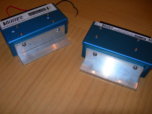
The Vantec Keycoder and speed controller were installed and wired up.


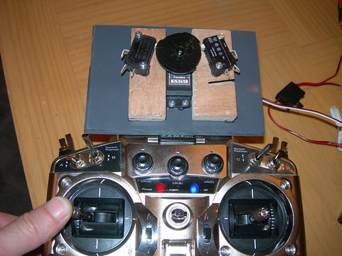
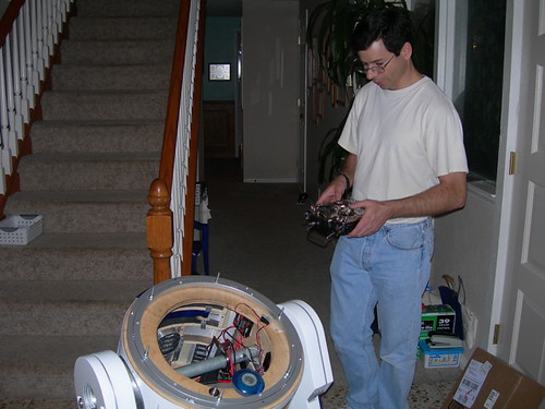
After a lot more work, it was finally time to try out R2. We powered up the receiver, main power and transmitter. The first thing I tried was the dome motor. It worked! Well, it worked backward, but it worked. William made some adjustments on the transmitter that reversed the behavior, and fixed things so that the dome motor turned properly. We could have swapped how the wires were connected on the dome motor, but this was easier.


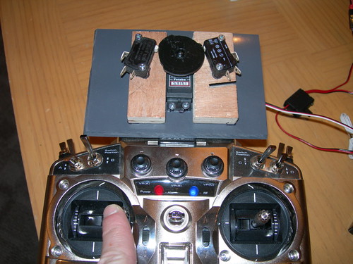
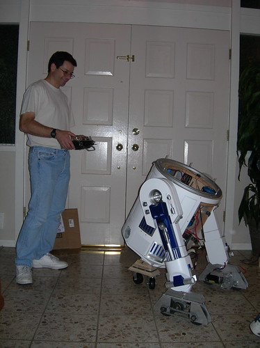
Next, I moved R2 forward. As with the dome motor, we had a connection that wasn't quite right on the speed controller. A quick swap of a connection, and R2 was moving like he should! I was all smiles.


No video to share yet, but I should have some in the next day or two.

The bad news: We blew up the CF Sound III card. We accidentally hooked it up to 24 volts, which is more than it can handle. I'm pretty sure the card is dead. I'll get a replacement some way or another. Oh well. If that's the worst thing that happens, I'll be a happy man.

R2 will spend the night at Mike's house, it was too late to tear him apart and pack him in the car by night's end. I'll pick him up Sunday and bring him home.

Thank you Mike, William, and Roy, for getting R2 that much closer to a dream come true!

Friday, April 27, 2007

Widened Dome Drive Groove in Frame, Finished Dome Drive Servo Mechanism

Tonight I fixed the problem with the dome drive wheel not grabbing the Rockler bearing as it spun. Sure enough, because I trimmed some of the edge off of the wheel to keep it from wobbling, I needed to bring the whole assembly closer to the bearing. The problem was that the shaft adapter was running into the groove in the frame that was meant to allow access to the bearing. So I widened the groove and now the dome drive works as it should.


Next, I finished up the servo mechanism that will trigger dome rotation.

I attached a couple of wooden blocks from behind with screws onto the PVC servo holder. Then I drilled pilot holes and screwed down the switches that will be bumped by the servo horn disc. The switches will be wired up to the dome drive motor.


Now, when the left stick on the remote is centered, neither switch is pressed.


When the stick is pulled to the left, the servo rotates and bumps the left switch.


When the stick is pulled to the right, the servo rotates in the opposite direction, and bumps the right switch.


Tune in again tomorrow, there may be some interesting developments.

Thursday, April 26, 2007

Roy's Leg Pipe, Started Working on Dome Drive Servo Mechanism

Roy Powers dropped by for a while, and he got to experience the joy of drilling through steel pipe. He needed to use my drill to get started drilling the holes in the steel pipe for the bolts that hold his R2's legs together. There's an inner and outer pipe that were drilled.


Meanwhile, I finally got to work on the servo mechanism for my dome drive. I started by filing some material off of the servo horn disc.


I iteratively filed the disc and fitted it on the servo, and used the remote control to turn the servo clockwise and counterclockwise. As the disc turns, it bumps into switches that will cause the dome motor to turn one way or the other, depending on which way the servo rotates and which switch (left or right) the disc hits as it rotates.


I removed a greater amount of material from the top of the disc, so that both switches are never pressed at the same time when the disc pivots. I plan to mount the servo, wooden switch holders and switches permanently to the PVC base tomorrow.

By the way, the dome drive wheel problem from yesterday may be due to the shaft adapter bumping into the frame. I'll Dremel a little more material from the frame and see if that solves the problem.

Wednesday, April 25, 2007

Goofed Up Dome Drive Wheel, Sanded Down Foot Shell Door Backs, Built Receiver Battery Housing, Attached Battery Boxes

Another day of variety.

First, I attempted to smooth out the wobble of my dome drive wheel ("attempted" should clue you in on where this is going). I clamped the motor in a vise, and held the Dremel with the drum sander next to the wheel, and fired up the Saturn wiper motor. The idea is that as the wheel turns and wobbles, the Dremel shaves some material off of the wheel, making for a smooth edge.


Unfortunately, my results were not so great. The wheel still has a slight wobble, and even worse, when I tried the wheel out with the dome drive on my R2, the wheel did not grab and spin the Rockler bearing consistently. I'm not sure if I can salvage this wheel. If not, I do have another identical, untouched wheel I can use, and I have already verified that I can remove the current wheel.


Mike had commented that the gears might bump into the inside of the foot shell doors, so while I had the Dremel out, I trimmed a little material off of the back of the doors, near where the gears are. I'm pretty sure the gears won't hit the doors now.


Next, I sawed and bent some aluminum angle bar to form the remote control receiver battery holder.


There will be an additional bar that goes across the front of the battery to keep it in place. This will be attached to the inside of my wooden frame.


Finally, I wrapped up by attaching the battery boxes to the foot shells. I drilled small pilot holes in the battery boxes.


Then I used wood screws with a long thread on them (not sure how else to describe them), to attach the battery boxes to the foot shells. The drivetrain still fits just fine in both shells, although I took the right foot's drivetrain out of the shell.

Tuesday, April 24, 2007

Started Dome Servo Mounting Plate, Trimmed Foot Shells for Drivetrain Gears, Removed Some Door Holders, Drilled and Pinned Dome Drive Wheel

Today I worked on an eclectic set of droid building tasks.

First, I started working on a mounting plate for the servo mechanism that will trigger the spinning of the dome. The mechanism's workings will become clearer over the next day or two, but this particular piece will house a servo.

First I traced the servo outline on the PVC mounting plate, and then I used the Dremel with the cutoff wheel attachment to cut out the rectangle.


The servo fits in just right. This will be mounted to one of the vertical wooden planks in my frame.


Next, I returned to the foot shells. When I installed the drivetrain chain the other day, I had to move a couple of the gears on each foot outward, causing them to interfere with the foot shells. I was able to trim a small amount of material from the inside of the foot shells with the Dremel drum sander, and now the gears fit inside the foot shells with a small amount of clearance.


I needed to remove the two bottom door holders on the back of each outer foot shell door, as these also interfere with the gears. I didn't consider the positioning of these very carefully when I first installed them. So I trimmed the holders off with the Dremel drum sander. Once I got down to the last sub-millimeter, I could just peel the rest off. I'll recut and reglue some new ones in better locations on each outer door shortly.


Finally, I wrapped up by pinning the dome drive scooter wheel to its shaft adapter.

A while ago I had drilled a hole into the wheel, and pushed some 1/8" diameter rod through to act as a set screw. I was able to pull that out and recycle the hole.

This time I drilled through the wheel and shaft adapter, much like yesterday's exercise.


Then I cut a new section of 1/8" diameter rod, and pushed it through the hole, pinning the wheel to the shaft adapter.


I need to do a little drum sanding on the wheel to ensure that there is zero wobble as it spins, and I need to install the spring that pulls the dome drive wheel into the Rockler bearing. Then the dome drive itself will be done.

Monday, April 23, 2007

Mounting Board for Sound Card, Drilled & Pinned Shaft Adapters, Drivetrain Finished

Tonight I made a little mounting board for the CFSound III board, so that the enclosure can attach to the inside of my frame.

First, I cut a spare strip of PVC to size.


Then I attached the PVC strip to the enclosure by drilling holes in the strip that match where the pre-existing screws on the bottom of the enclosure go. Now the PVC strip gets screwed onto the back of the enclosure. I also drilled a couple of mounting holes on the ends of the strip, so that I can mount the enclosure onto one of the wooden vertical planks of my frame.


Next came a part of the drivetrain build that I had been fretting over for quite a while, the drilling and pinning of the shaft adapters to the Saturn motor shafts. It turned out that I had nothing to worry about, it was not as hard as I thought it would be.

I clamped down the shaft adapter in my drill press vise, and then secured the vise to the table. When I was sure that the drill bit was ready to go dead-center through the shaft adapter and shaft, I fired up the drill press and slowly drilled a 1/8" diameter hole through it all.


I got the hole just where I wanted it, toward the very bottom of the shaft adapter, near the thickest part of the motor shaft, and right through the middle.


In all, I drilled the two foot motor shafts, and the dome drive motor shaft. I still need to drill another hole in the dome drive shaft adapter to secure the dome drive scooter wheel to it. I'll deal with that soon.

Next, I JB Welded a 3/4" long, 1/8" diameter steel pin into each hole. The steel pins are from McMaster-Carr, and only come in quantities of 100. The pin will secure the shaft and shaft adapter together, so that the two won't shear when the motor torque kicks in.

It's important to secure the pin to the thickest part of the motor shaft, as the threaded area of the shaft has been shown to be too thin and/or weak to handle the stress when running the motors at 24 volts.


And with that, my scratch-built Heath & Alex drivetrain is done! I'll put it all back together again once the JB Weld has dried.

Sunday, April 22, 2007

More Parts Shopping, Worked on Shaft Adapters, Vantec Mounts, Rockler Bearing Screws

Today I picked up a bunch of 30-amp fuses from Kragen, and some tie-downs for the wire from Home Depot, so the remaining items on the shopping list is getting shorter.

Just when I thought I was done sawing steel, I found that the dome drive shaft adapter was just a little too long, it was hitting the D-cell battery holder in the dome as the dome spun. So I sawed that down, and now the dome spins freely.


I also sawed open the dome drive plate, so that I can get the motor in and out of the assembly. With the shaft adapter permanently installed (see below), I did not want to lock this in place for eternity. Hopefully now I'm done sawing steel, for a while at least.


Of course, there's always aluminum to saw. I'm using 1" angled aluminum to mount the Vantec speed controller and Keycoder.


After cutting the aluminum to size, I drilled and installed it with #6 screws.


The bare side of the aluminum will be screwed onto the inside of my wooden frame.


I JB Welded the two motor shaft adapters and the dome drive shaft adapter to their respective Saturn wiper motors.


I will also drill a 1/8" diameter hole near the base of the shaft adapter, and insert and JB Weld a 1/8" steel pin, to help secure the shaft adapters to their shafts.


Finally, I picked up some #10 lock washers and installed them on all six screws that secure the dome to the Rockler bearing. With the lock washers installed underneath the bottom nut on each screw, the screws are now on the bearing nice and tight.

Saturday, April 21, 2007

Electronics Shopping, Dome Drive Shaft Adapter Fixed

In preparation for R2's first steps, Mike and I went shopping for things like wire, switches, fuse holders, and other related items. We ended up going to Radio Shack (spare battery holders, switches, 12 gauge wire), a local electronics store named Orvac Electronics (CAT5E cable with multiple strands for wiring up sound, fuse holders, main circuit breaker, wire connectors), and Home Depot (power blocks).


I still need to buy some 30-amp fuses and some tie-downs for the wires.

The other day I tried drilling the shaft adapter for the dome drive, but either the drilling or the tapping (or both) turned out crooked, so the shaft adapter wobbled as the motor turned. Mike helped redrill and retap, and the result was a much cleaner rotation.

Rather than tapping by hand, Mike had the idea of putting the tap onto the drill press and manually turning the chuck to tap the hole. That way, the tap would go in at exactly the same angle as the hole that was drilled on the drill press. It worked out well.


I still have a ton of work to do before the droid is wired up for movement. I have to build a small assembly for the dome drive electronics. I also need to set up a mount for the sound board. And I still need to pin the shaft adapters to the motor shafts. Looks to be a busy upcoming week.