Monday, February 28, 2011

Finished Cutting Battery Box Doors, Cut and Glued in Battery Box Door Holders

Tonight I did a little work on the battery boxes.

In January, Mike Senna had cut the maintenance doors 99% of the way, so I used a utility knife to finish the cuts in the corners. These are Craig Smith's PVC battery boxes, truly works of art.


Next, I cut some scrap PVC for the door holders.


Then, I glued the holders on the inside of the corner area of each battery box.


Once these have dried, I can lay the doors back in place, and drill holes for the screws that will attach the doors to the battery boxes.

Saturday, February 26, 2011

Finished Up Drivetrain Channel Work

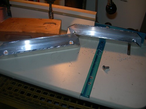
Today I wrapped up work on the foot channels for the drivetrains on the outer feet.

I went over to my friend Kelvin's house to have the 1/4" holes that are used to attach the channel pieces to the main drivetrain bodies countersunk. The countersink bit I have won't reach that deep into the channel.


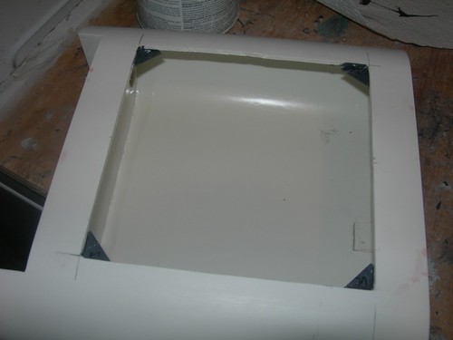
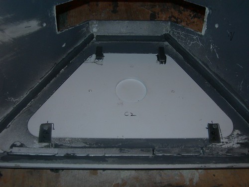
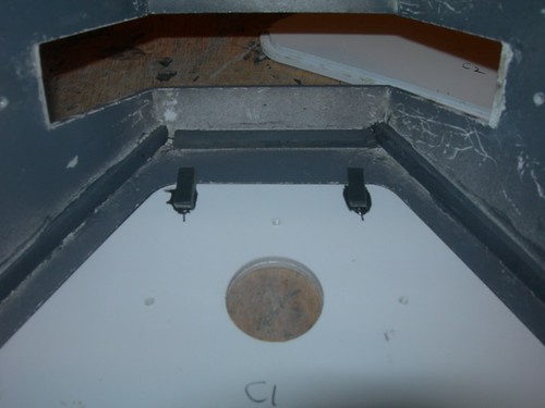
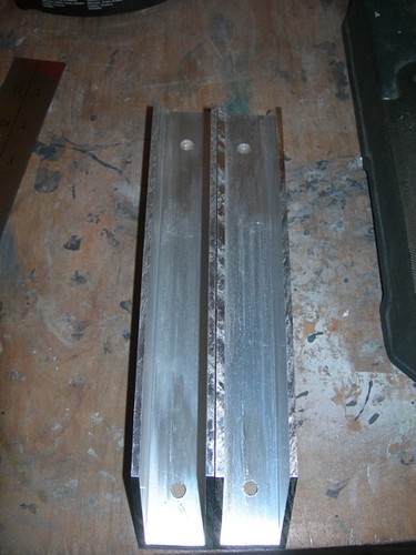
All four holes are ready to accommodate the 1/4" screws.


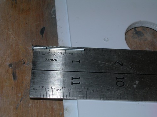
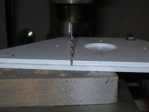
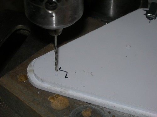
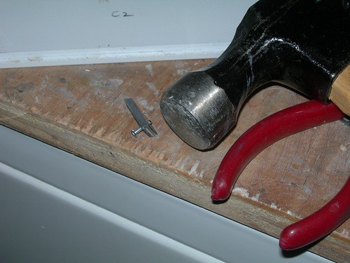
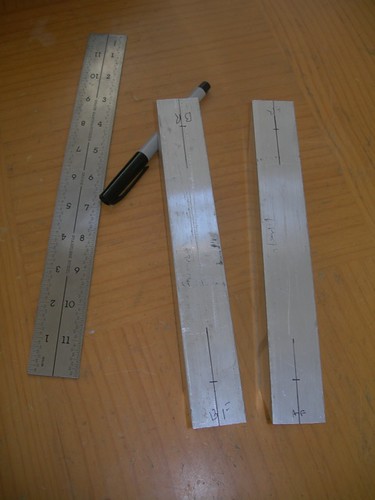
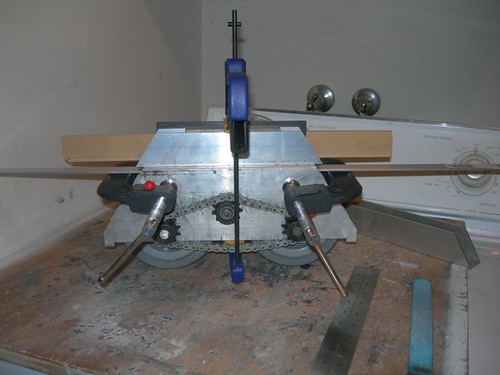
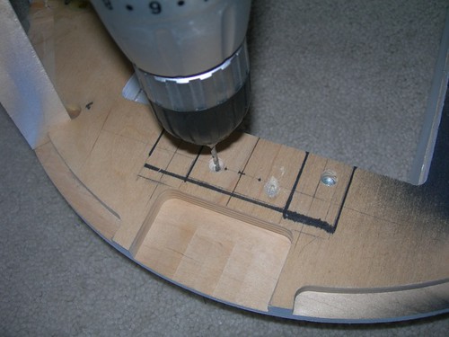
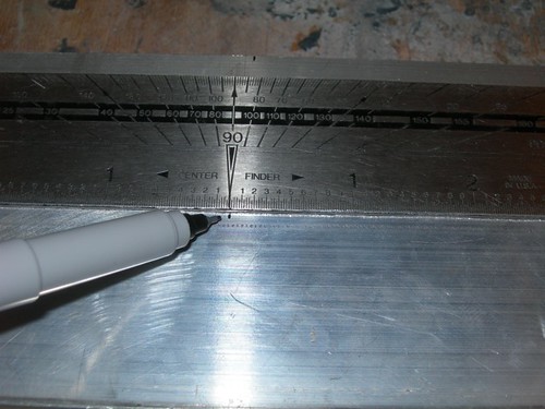
Back home, I worked on drilling the holes in the channel for the ankle bolts. First, I measured and marked the center point at the top of the channel.


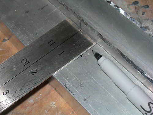
Next, I measured 5/8" down from the top, and marked the spot to drill. The 5/8" measurement seems to work well for droid #1, so I'm using it again. It's high enough that the ankle bolt hole in the actual wooden ankle allows parts such as the ankle cylinders to clear the top of the foot shell, yet low enough that I can get a wrench into the footshell to tighten or loosen the ankle bolts without too much fuss.


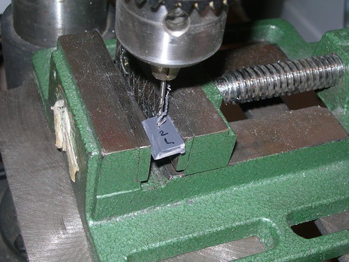
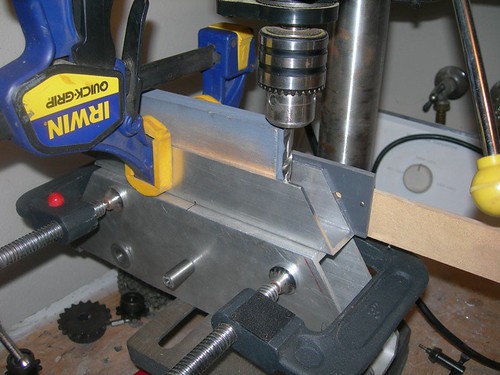
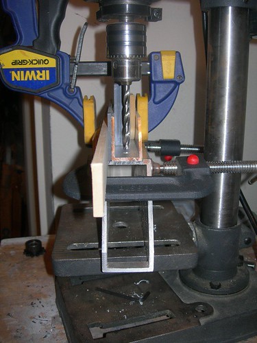
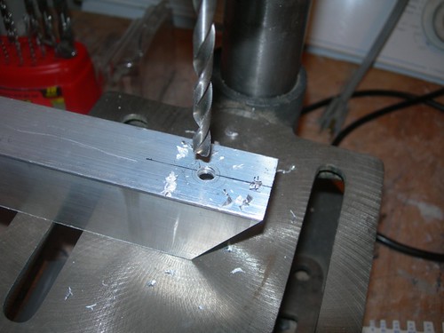
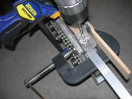
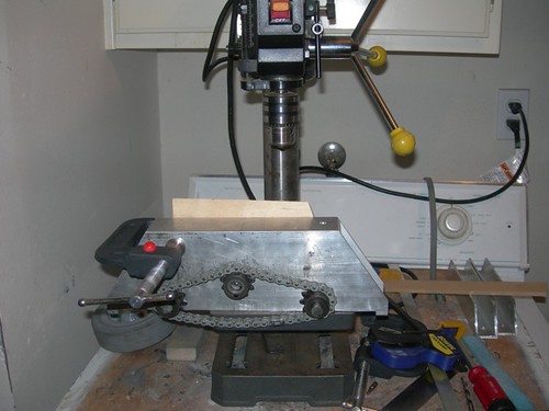
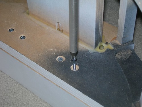
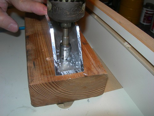
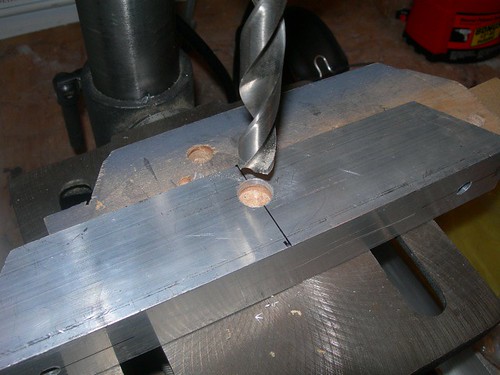
Time to drill. I will be using a 1/2"->3/8" bushing for the 3/8" ankle bolt, but I decided to start drilling with a 1/4" drill bit, and follow-up with the 1/2" drill bit.

The 1/4" hole is done.


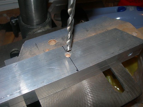
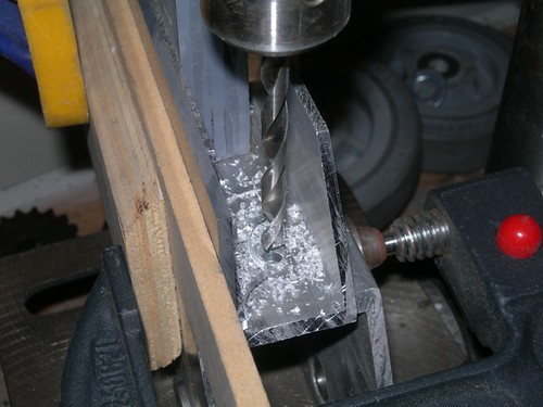
And the 1/2" hole is done as well. The bit self-centers in the hole with very light pressure on the drill press handle.


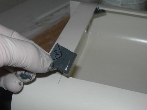
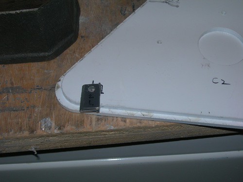
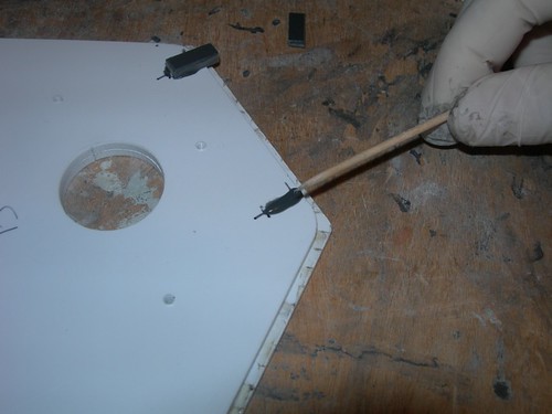
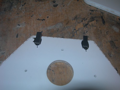
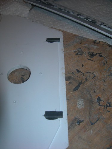
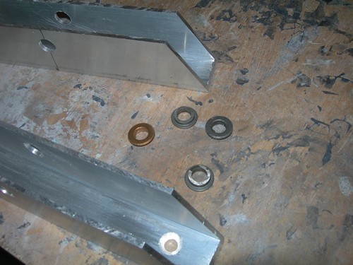
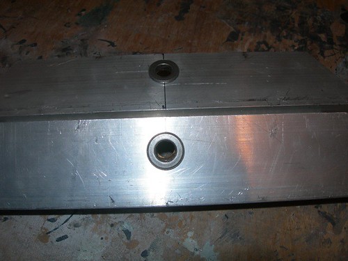
I pressed the bushings in place. Once these are installed on the droid and the ankle bolts are tightened down, they won't have anywhere to go.


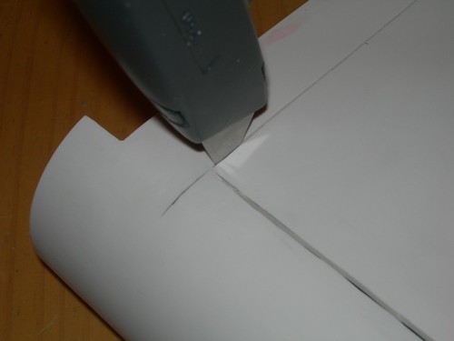
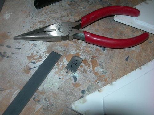
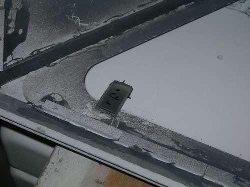
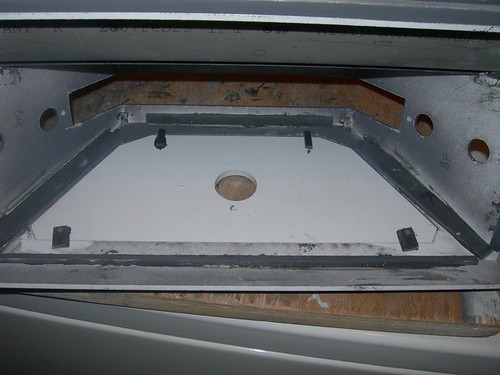
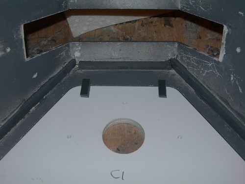
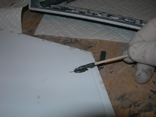
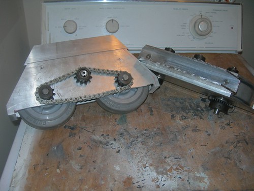
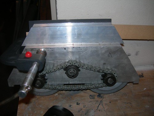
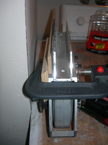
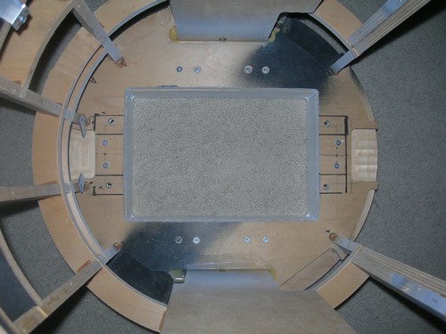
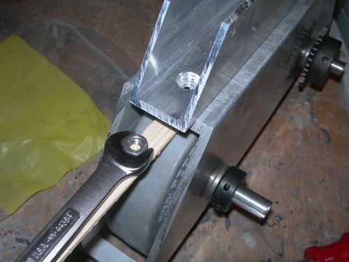
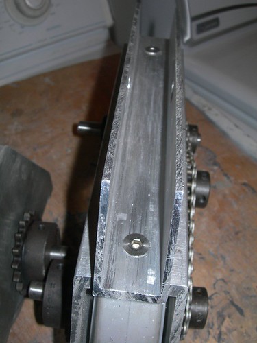
Finally, I screwed down the channels to the main drivetrain body pieces. It can be tricky to get the nut to stay in place, so I used a thin strip of wood to support the nut under the hole.


This is probably as far as I'm going to take the drivetrains for now, until I decide to R/C droid #2. Still to be done is the locating and installation of the motor-mount bracket, but as I say, that will wait until I need it.

Thursday, February 24, 2011

Finished Working on Foot Shell Door Holders

Tonight I wrapped up work on the foot shell door holders.

I started by cutting eight segments of PVC for the bottom of each foot shell door. These are a little wider than the segments I cut last night for the tops of the doors.


I then did a loose fit of each segment to see where it should be located, and to mark the point at which to drill.


I measured 5/16" on each nail that I'm using to secure the PVC segments, as this is the length to which the nails will be trimmed.


I used pliers to cut the nails to size.


Next, I drilled 1/16" holes through each of the PVC segments, just wide enough to allow the nail to fit snugly through.


I set the drill press stop to go as deep as the upper 1/8" layer on the inside of the foot shell door. The PVC segments are also 1/8" thick. The 5/16" length I cut the nails to allows for a little slack.


I then drilled all the points that I had marked earlier.


I hammered the nail segments through the PVC segments, such that they barely showed through to the other side of the PVC segments.


Then I finished the job by nailing the PVC segments to the inside of each foot shell door, where had I pre-drilled the 1/8" deep holes.


Looks like it works! Both doors on the center foot shell are locked in. To release the doors, the bottom PVC segments are simply pivoted 90 degrees.


As are the doors on both outer foot shells.


There is still plenty of painting to do. I hope the weather cooperates this weekend, but that doesn't look very hopeful at the moment.

Wednesday, February 23, 2011

Glued in Top Door Holders on Foot Shell Doors

Tonight I worked on attaching the doors that go on the foot shells.

I am using scrap PVC sticks left over from the foot shell build of droid #1 for this job. They just need to be cut to size.


Starting with the center foot shell, with the door in place, I did a loose-fit of where the PVC segments needed to be.


I marked the spots with a pen, and used a toothpick to apply PVC glue to the inside of the foot shell door.


Then, it's just a simple matter of gluing the segments down.


The gray PVC segments rise just a little above the door alignment layer, enough to keep the door against the door frame on the foot shell.


Same exercise for the outer foot shells.


I still need to nail in the two PVC segments on the bottom of each door. These will pivot on the nail to allow the door to be locked and unlocked from the foot shell. I hope to get to that shortly.

Tuesday, February 22, 2011

Finished Drilling Drivetrain for Channel Pieces

After deciding to not rush the drilling of the drivetrain for the top channel pieces last night, tonight I removed the chain and gears on the two drivetrains and got back to work.


I sandwiched lots of things together to get the channel piece centered. Similar to last night's effort, I clamped a piece of 1/2" plywood to the main drivetrain body, with a portion of the plywood rising above the top of the main body. Next to that, I placed a 1/4" piece of MDF, followed by a 1/8" piece of PVC, to give me my 3/8" spacing from the edge of the main body for the top channel piece. I also wedged a 3/4" piece of plywood and a 1/4" piece of MDF into the channel itself, to help keep the channel from bending as I applied a clamp to all that work.


With center of the channel piece aligned to the center of the main drivetrain body, it was time to drill the 1/4" holes on the drill press.


Four holes later, and the two channel pieces were attached to their respective drivetrain bodies.


I still need to countersink the holes in the channel pieces, but I'll have to wait to borrow my friend Kelvin's countersink bit, as the one I have won't reach that deep into the channel.

Monday, February 21, 2011

Drilled Drivetrain Channel

Today I did a little work on the drivetrain for droid #2.

I started by measuring where to drill the holes in the channel pieces that go at the top of the drivetrain. These will be screwed to the main drivetrain body using 1/4" screws and nuts. The target is 1" from each end, centered in the middle of the width of the channel.


I used the drill press to drill these holes.


All four holes are drilled in short order.


Next, I wanted to clamp the channel pieces in place, and use them as a template for drilling the holes in the main drivetrain body. First, I marked center alignment points for each piece.


I also clamped a piece of plywood to the side of the drivetrain, and wedged a 1/4" piece of MDF and a 1/8" piece of PVC between the plywood and the channel, to perfectly center the channel piece on the main drivetrain body. There should be 3/8" on each side of the channel.


I then clamped down the channel and prepared to drill, using a hand drill. The wheels and gears make it impractical to put this on the drill press as-is.

It's almost art.


Unfortunately, my almost-art project didn't work out so well. As I was drilling with the hand drill, the whole drill and bit wobbled quite a bit, as I was struggling to keep everything steady while holding the work down on its two wheels. I could tell this approach was not going to work.


I revisited the drill press. This meant removing the wheels. I realized that I'd have to remove the gears as well.


At this point, I looked ten minutes into the future, and saw disaster. I decided to stop in my tracks, get a good night's sleep, and continue tomorrow. It's the discretion/valor thing.

Saturday, February 19, 2011

Attached Skirt to Frame, Adjusted Yellow LEDs on Rear PSI

Today I finally got around to attaching the skirt to the frame. I had drilled the frame back on December 26, 2010, but for whatever reason, I postponed drilling the skirt supports to attach the skirt to the frame.

I centered the skirt underneath the frame, and drilled pilot holes using a 7/64" drill bit for the #8 x 1.25" screws I am using to attach the skirt to the frame.


I screwed in each screw by hand with a screwdriver. In retrospect, using the drill might have saved me a blister or two.


Twelve screws secure the skirt to the frame. It's not going anywhere.


I turned the frame over to inspect the results. Everything looks nice and centered. A combination of a weird perspective and shadows produced from the camera flash gives the whole thing an odd look.


In the evening, I turned my attention to the yellow LED on the rear PSI. I had noted earlier that it wasn't bright enough, so I decided to replace it with three 7000mcd, 2.6Vf, 30mA yellow LEDs.


Of course, this means I needed to swap out the associated 1Kohm resistor. Ideally, I'd be using a 47 ohm resistor, but the closest I had was a 62 ohm resistor, so I used that. I may go resistor shopping to see if I can do better sometime later.


I also needed to swap out the associated 10 µfarad capacitor with a 100 µfarad capacitor, to get the blink rate right.


The verdict? It's definitely an improvement. Can I live with it? I think I can for now, but I certainly reserve the right to revisit this in the future.