Monday, March 31, 2014

Started Mounting Electronics to New Electronics Board

Tonight I started the task of mounting the electronics on the new electronics board for droid #2.

I spent quite a bit of time loosely laying out various configurations, before settling on a placement that I hope will work well.


Time to start drilling. I used various parts as templates for where to drill.

The attachment for the speed controller.


The large hole for connectors to pass through.


Using the dome controller mount plate as a template.


Finally, I used the mounting holes on the Stealth hardware as a guide to mark where to drill, and then drilled the three holes for the DC converter, and the four holes for the Stealth Receiver.


For the Stealth hardware, I'm using #4 screws from underneath, and nylon standoffs and nuts, in order to avoid having metal contact metal. Also, I chose longer screws in case I decide to cover these electronics with plexiglass.


The electronics board, as it currently stands. Loose wires will be cut to size and soldered and/or attached to their mount points, which should help clear up the clutter.


And the electronics board, as I hope to have it in the next day or two.


Sunday, March 30, 2014

Cut New Electronics Board

I decided that I'm going to have a new electronics board cut for droid #2. I picked up some 5/32" thick plywood, and went over to my friend Kelvin's for the cutting, since he has the table saw that I was borrowing from him for years.

The first step was to cut the correct size rectangle.


The corners need to be cut from the bottom edge, in order to accommodate the batteries at the bottom of the droid.


Done. The old board and the new one.


Back home, I did a test fit. Battery clearance looks good at the bottom.


And the fit in the slots in the frame looks good at the top.


Next up, mounting the electronics.

Wednesday, March 26, 2014

Depopulated Electronics Board for Droid #2

They say sometimes you have to move backward to move forward. I hope that's true in this case.

The layout for the electronics panel for droid #2 definitely needs to be redone. I decided to pull almost everything of it. That includes the Dome and Sound Automation board (which I plan to leave off for now), the Stealth controller electronics, the amplifier, and the speed controller. The CF Sound III was removed the other day, and it will also likely stay off.


I also marked the lower corners of the board, where I need cutouts for battery clearance at the bottom of the droid, and marked "margins" along the sides where I cannot place anything, as that would interfere with the way the board slides into the slots in the frame. The only thing remaining on the board is the dome controller, and I am seriously thinking of relocating it too.


I want to lay this out as neatly and as logically as possible, so I'm going to think about this for at least a day or two. I would also like to accommodate future options, such as repopulating the Dome and Sound Automation board and CF Sound III, if I wish to in the future. Also, there's part of me that says maybe I should chuck the electronics board and mount stuff to the frame, as is the case for droid #1, but there are a couple of huge advantages to the board. One, maintenance is very easy, and two, I rarely need to take the back door off to get to whatever I need to work on. Another concern I have with this board is that I think it will interfere with a droid lift that I may add to droid #2 in the future.

Tuesday, March 25, 2014

Wired Electronics Board for Second Battery Bank on Droid #2

Tonight I wired up the electronics panel on droid #2 to accept a second set of 12 volt batteries that will be connected in parallel with the first set.

Currently (pun?) the power comes from a single set of batteries that supplies 12 volts. The existing battery connector needs to be cut so that I can solder on an additional connector for the second set of batteries. I removed the electrical tape and shrink tubing first. The other connector in the picture is for the dome motor.


After cutting the original connector off, I prepared to solder the old and a new connector in parallel. I worked on the positive (red) wires first.


The positive wiring is soldered and shrink-tubed. The negative black wires are soldered and about to be shrink-tubed. It's just about impossible to see, but there are two black wires on the left, soldered onto the wire on the right.


And done with that little job.


Plenty more to do elsewhere though.

Sunday, March 23, 2014

R5-D4's First Steps

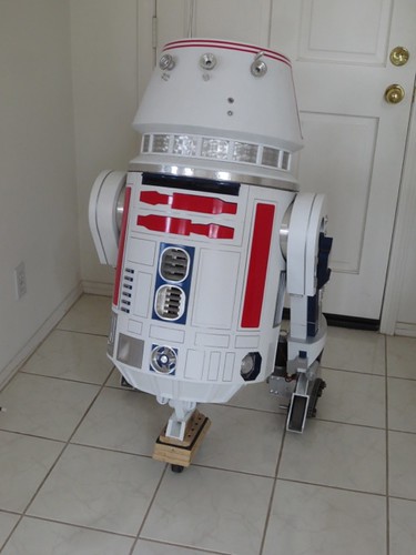
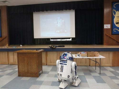
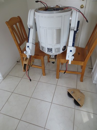
Today was a bit of a milestone for droid #2, as he took his first steps, dressed as R5-D4. These also may be his last steps for a little while. Nothing particularly bad happened, but today's efforts showed me I still have some work ahead of me, which I'll get to shortly.

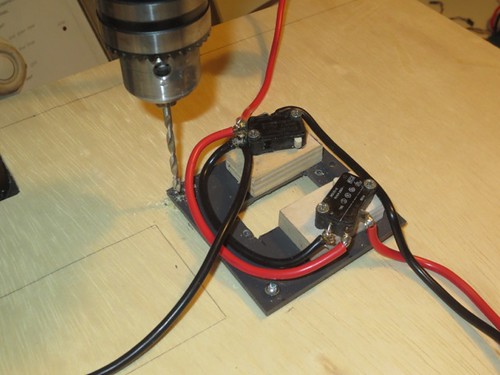
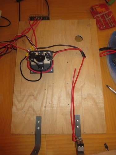
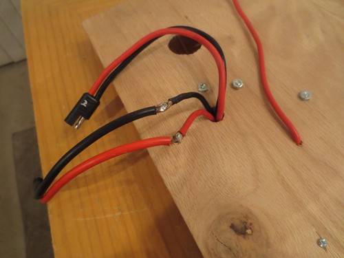
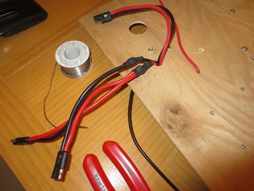
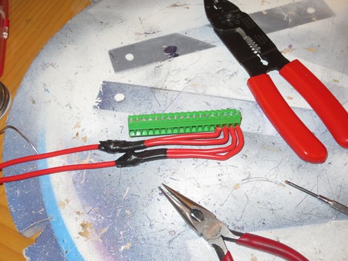
First, I installed the connectors that lead to the motors into the speed controller.


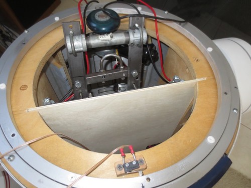
Time to slide the electronics panel into the droid.
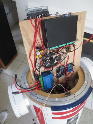


Oh. Oops.


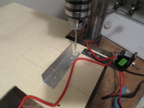
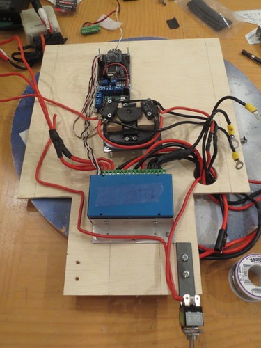
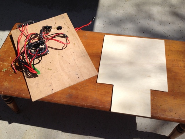
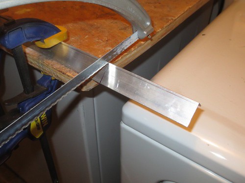
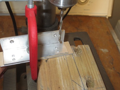
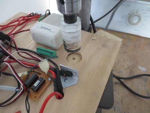
Okay, fine. I relocated the speed controller as far to the center as I could (which wasn't very far, but was just far enough).


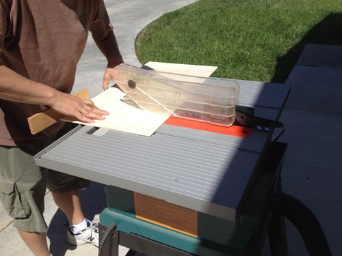
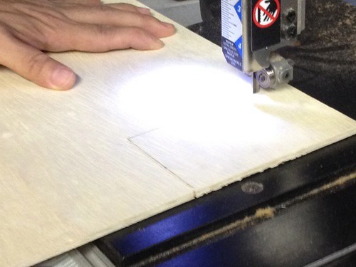
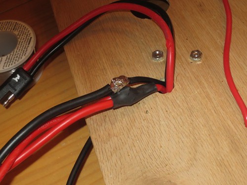
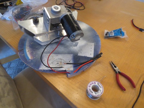
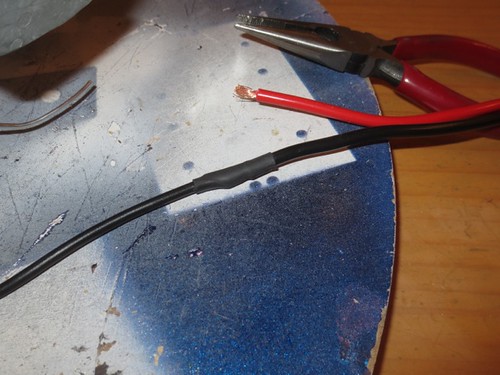
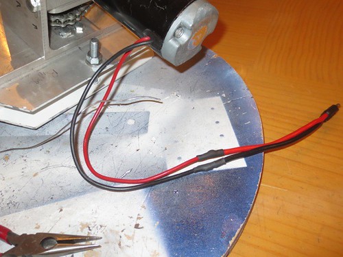
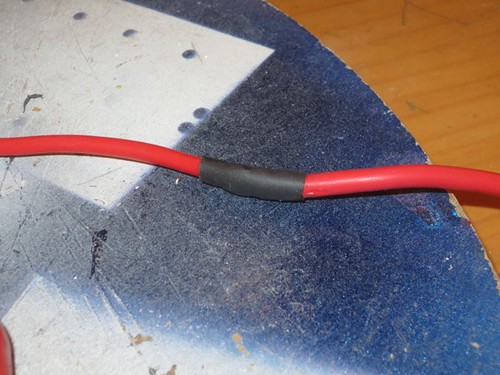
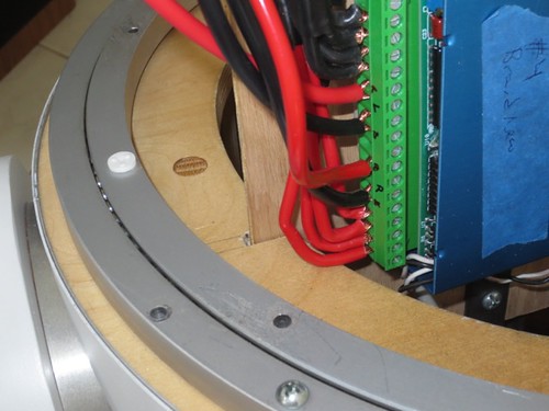
While I was drilling holes to relocate the speed controller, I also used the hole saw to drill a large hole to allow the motor wires to pass through.


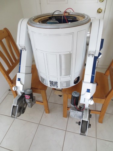
Time for new shoes! Out with the old…


... and in with the new. I have not built or installed ankle locks yet, those are still to-do.


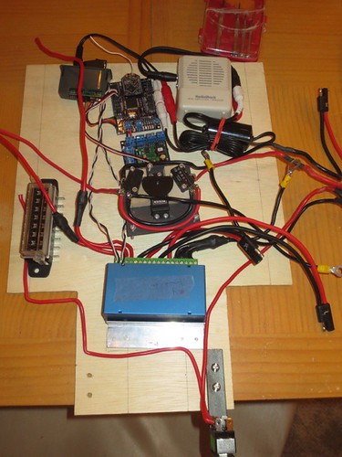
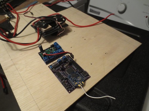
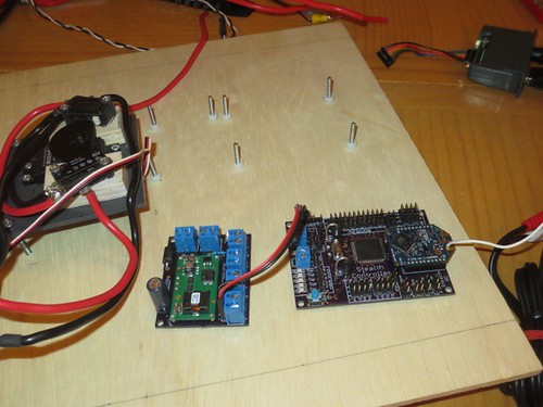
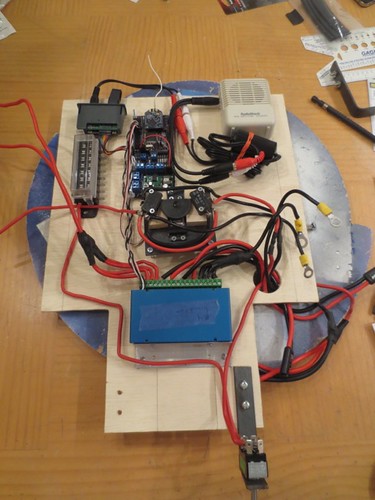
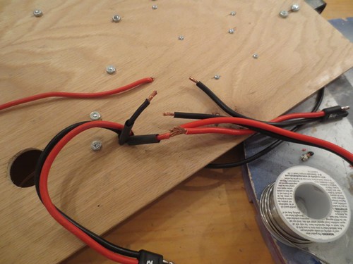
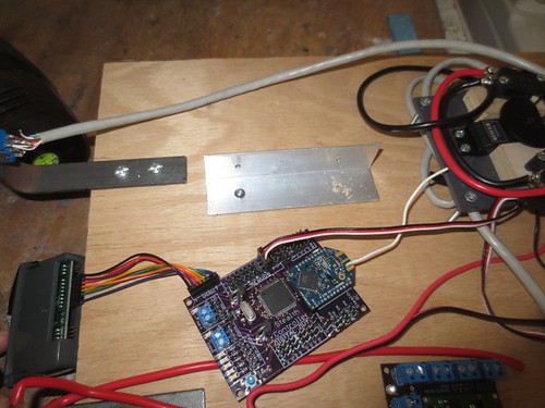
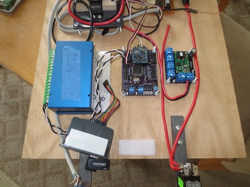
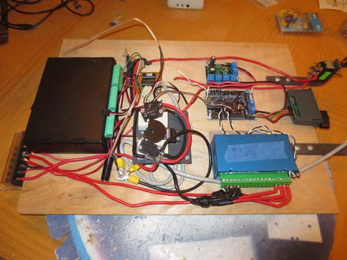
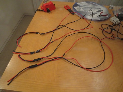
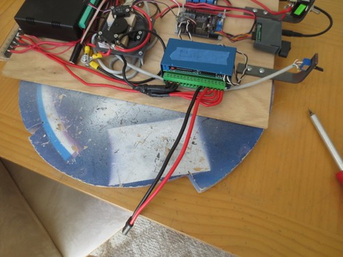
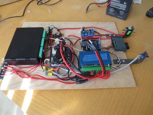
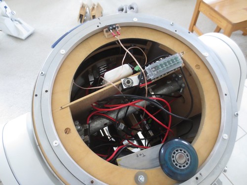
I installed the rats nest of my electronics board.


Stealth transmitters are on, and we are ready go!


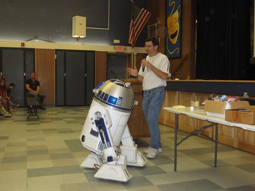
His first steps were fairly successful, but I think he's drawing more current than one bank of batteries can supply, as power cut out to the Stealth receiver board.

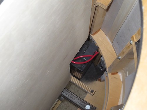
Normally I use two pairs of 6 volt, 12 amp-hour batteries. Each pair is wired in series, and the two pairs are wired in parallel, which provide the 12 volts. For this test I only used one pair, as I haven't done the wire-up for two pairs in parallel yet. In my bench testing I used a beefier battery that doesn't fit in the droid.

Also, the electronics board is a messy problem. The problem part is that when I install two pairs of batteries, the electronics board runs into the second pair sitting at the bottom of the droid. It can clear one pair though. I didn't leave room at the bottom of the board to allow me to cut out the areas that interfere with the batteries, so I will need to redo the board to some extent, which probably means that some of the wiring I've been doing these last few days will also need to be redone, although some of it may be salvageable.

Anyway, for this little test, things worked well. I also turned the dome under remote control, and sounds played, so overall things are looking positive. Nice job R5-D4!


Saturday, March 22, 2014

Attached Components to Electronics Board for Droid #2

Today I worked on populating the electronics board on droid #2 with some of the components that will bring R2 to life.

This means locating the speed controller, Stealth receiver, power supply board and the VMusic2 board. I used a hand drill to drill holes in the electronics board.


The VMusic2 cover doesn't have any mount points, so for now it's held on with Velcro. The ampilifier may also end up getting attached with Velcro as well. Everything else is screwed down.


I wired up the positive and negative connections for the Vantec RFDR23 speed controller. This took a lot longer than it probably should have.


I still need to hook up the wires that go to the foot motors to the speed controller, and I need to mount and hook up the amplifier to the VMusic2. At that point, things may be read to test on the droid!


Wednesday, March 19, 2014

McPherson Magnet School Career Day

Today R2 and I were invited to McPherson Magnet School for their Career Day. I was to give three presentations to about 800(!) kids total, in grades 2-8.

I arrived about a half hour early for my first presentation at 10:30am, and set up. The lights were dimmed once my presentation began, so that the slide show could be seen more easily.


I prepared two separate presentations, one geared toward the younger students, and another geared toward the older ones. I'm a software engineer, so the beginning of my talk described my education and my job, and then I segued into the discussion about R2, since that's what the kids really wanted to hear about anyway. I also demonstrated the Arduino system and talked about how it's relatively easy nowadays to get started with embedded programming.


Like I say, lots of students! And this was just one of the three presentations.


Since not everyone could see R2, I drove him down the aisles so that they could get a better look and take pictures. To my relief the students were all very well behaved, and R2 survived the excursion with no missing parts.


At the end of each session, I did Q&A. Students were selected by the staff to come up and ask questions, which were all good ones.


I'm really glad I was able to come out, and hopefully students interested in programming and/or robotics will be motivated to pursue such a hobby.

Soldered Connectors to Motors for Droid #2

Today I soldered the connectors onto the motors for droid #2. You have to admire my laziness, I didn't even bother to remove the motors from their drivetrains.


By now this should look familiar, and it doesn't get more interesting than it was earlier in the soldering process. Solder wires together...


... and shrink-tube them. The most amazing thing about this process is I didn't forget to loop the segments of shrink tubing onto the wires before soldering even a single time.


Same for the red wires.


And done. Once I did the second motor, that is.


I think I'm done with the wiring from the speed controller to the motors. I still need to work on the electronics panel to get the speed controller and Stealth Controller/power supply board/VMusic2 board installed.

Monday, March 17, 2014

Continued Soldering Wires for Drivetrain on Droid #2

Welcome back to the exciting world of soldering, as I return to work on the wiring for droid #2. Actually, with me it can be exciting, as you never know if it will end up right.

One long piece of 10 gauge stranded wire, ready to be soldered to a 10 gauge connector.


And now, ready for shrink tubing.


And now, ready for electrical current.


I finished soldering the connectors to both pairs of wires that will run down each leg. The connectors on the other ends will attach to the speed controller on one end, and the motors on the other. Thus, I still need to put connectors on the motors, and I need to add the wires to the speed controllers to the other connectors. Getting there, slowly but surely.


Sunday, March 16, 2014

Cut Aluminum Angle Holder for Speed Controller, Started Soldering for Drivetrain Wire-up on Droid #2


Today I put in a little more work on the effort to get droid #2 mobile.

I'm going to need to attach all sorts of stuff to the electronics board, including the Vantec RDFR23 speed controller. I cut a piece of angled aluminum that will screw onto the speed controller for this purpose.


I used the angled aluminum that holds the same speed controller on droid #1 as a template for where to drill the holes. I'll have more drilling to do for the screws that will hold it onto the panel, but at least the holes for the speed controller side are ready for the short #6 screws.


Next, I started soldering up the wiring that will run down the legs. I used 10 gauge stranded wire for both the wire that runs down the legs, and the connectors that will provide the plugs on both ends.


It ain't pretty, but she'll hold together. (Here me baby? Hold together.)


Shrink tubing insulates the work, and also helps things hold together.


The job on the black wire was slightly less ugly.


I'm hoping to get more of the wireup done during the week, but we'll see.