Sunday, July 31, 2011

Started Working on Replacement U-Bolt, Back Door Strategies at Matthew's

I need to replace the U-bolt that goes around the gas pipe for droid #2. I apparently managed to strip the threads quite some time ago on one of the legs. Furthermore, one of the legs needs to be cut down to avoid interfering with some of the nuts on the back of the electronics panel that help secure mounting screws on the other side.


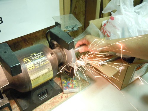
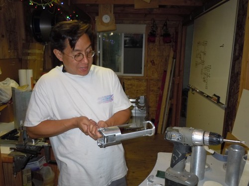
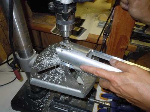
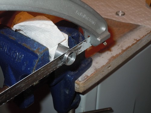
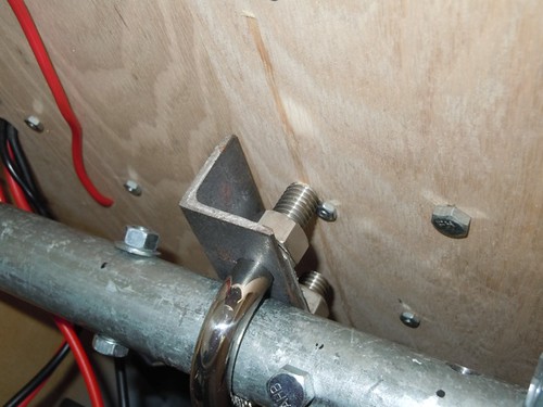
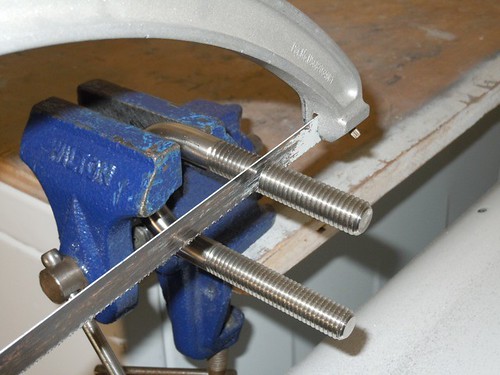
I have an extra U-bolt, so I started hacking it down to size. Even without the electronics panel, the bolt needs to be cut down to accommodate a socket wrench.


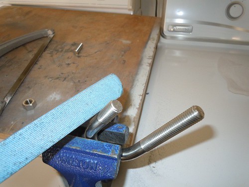
The top also needs to be filed to more easily get the nut on.


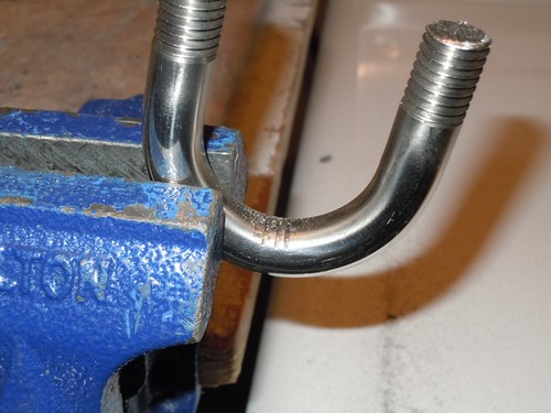
I also started hacking notches on the "U" portion, which helps with friction around the gas pipe. I ran out of time before I got very far.


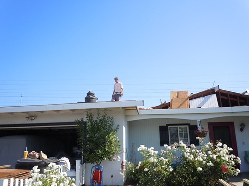
Next, it was off to Matthew Henrick's, where he is re-reoofing his house himself!


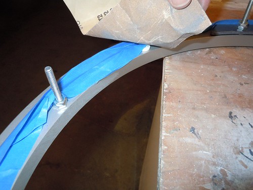
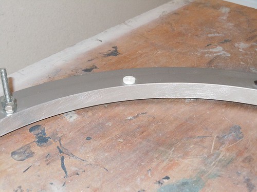
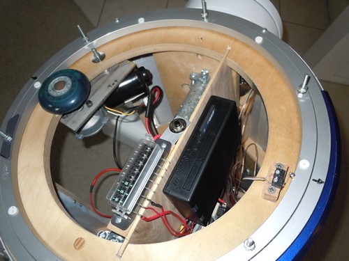
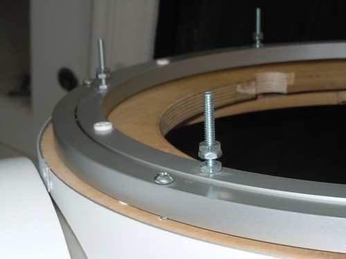
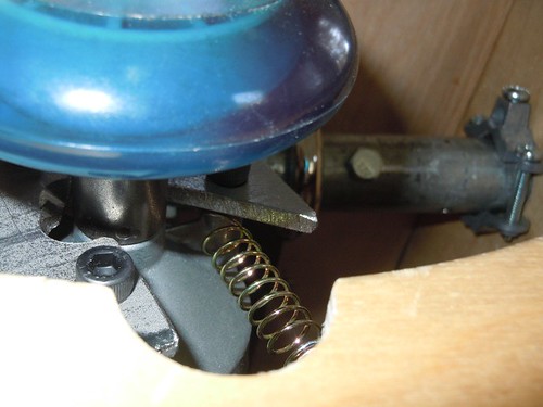
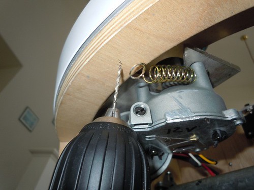
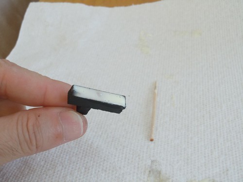
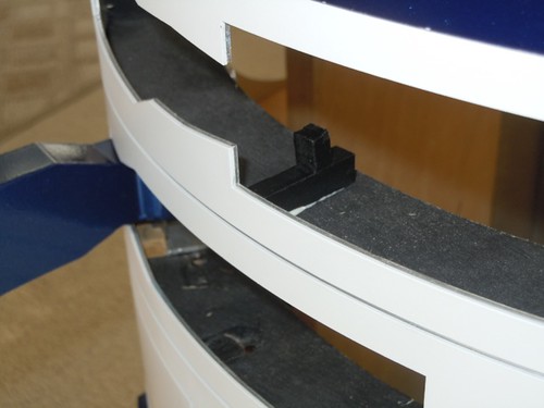
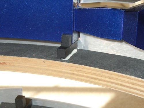
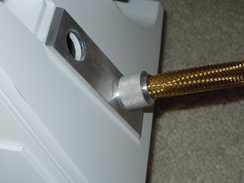
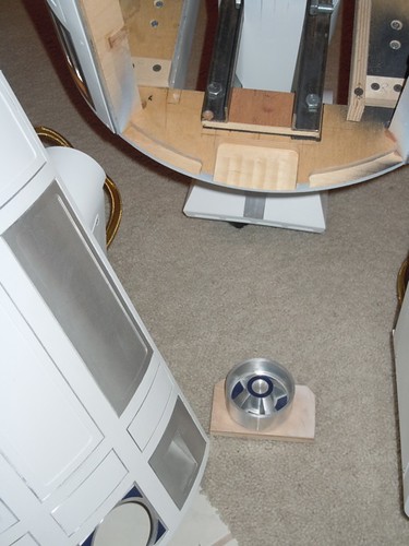
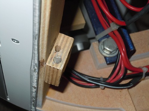
I'm considering using magnets to mount the back door on droid #2, so I wanted to check out Matthew's setup, which is based on Frank Cerney's. Matthew attached a wooden rib to the inside of the back panel, toward the bottom. On the underside of the rib is a steel pin and a screw on each side.


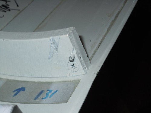
This attaches on the frame to a matching hole for the pin, and a rare earth magnet for the screw head.


Likewise, there is another rare earth magnet that magnetically attracts a steel washer that is attached near the top of the door on each side.


Matthew reports he's had no trouble with this setup.

I see the pros and cons of this approach versus using screws, which I use for droid #1.

With screws, you never have to worry about the door falling off, or possibly some curious kid (or adult) pulling the door off unexpectedly.

On the other hand, with screws, you had better have a screwdriver handy if the door needs to be removed, and it does not come off quickly. There are times I've needed to take the door off droid #1 for a quick autograph or some maintenance job on short notice.

Since droid #1 will probably be the droid that goes out in public the most, and because I can always try the screw method later, I am likely to try the magnet approach first with droid #2, and see how it goes.

Saturday, July 30, 2011

Yet Another Circuit Repair

So last night I lightly sanded the inner perimeter of the Rockler bearing with 150 grit sand paper, to help give the dome drive wheel some traction. Of course, I covered the race with masking tape to protect it from the dust.


After cleaning up the dust, I removed the masking tape, and the surface looked sufficiently scuffed.


I reinstalled the bearing on the droid and tried it out. It was working great, no wheel slippage, everything was fine... until I heard a loud pop! and smelled the wonderful odor of some burnt electronic component. I immediately powered off, too disgusted to diagnose what blew up this time.

Today I pulled the electronics board out, and discovered the problem. Neither Mike nor I realized this past Tuesday that one of the two decoupling capacitors (the 0.33µF) was a tantalum capacitor, meaning it has polarity, unlike the 0.10µf ceramic capacitor, that has no polarity. Of course, odds being 50/50, the capacitor was installed backwards and survived a few days until it could take no more. Thus, the source of the bang and smell.


Fortunately, I purchased two of these guys, so I pulled the spare out of the package. Yup, one lead is longer than the other, and there is a "+" on the markings.


I actually managed this minor surgery on my own. I replaced the capacitor, using the proper polarity this time.


I hooked everything back up in the droid, and the circuit ran flawlessly and the dome wheel never slipped for forty-five minutes, until I got tired of hearing him and turned it off. So until the next time something blows up, I hope to leave the electronics alone for a while.

Friday, July 29, 2011

The Big Droid Put-Together - The Movie

Just for fun, I did a time-lapse of the final assembly of droid #2.


Pictures were taken once per minute. There are a total of 941 pictures, or 15 hours and 41 minutes worth of assembly.

Unlike droid #1, which I built from the ground up as I went, with droid #2 I only fit together adjoining parts to see if they would work together. I held off final assembly until the very end. This was partly to make accessing individual parts easier as the build went along, and because I didn't want to have a partial droid sitting around staring me in the face all the time.

I'm still not quite 100% done with this droid. I need to install the back door and rear power coupler, and glue down the backing strips for the ankle brackets. At that point, I'll consider it done. Soon, soon...

Wednesday, July 27, 2011

Installed Electronics Panel

Tonight I had a chance to install and try out the electronics panel for droid #2. This time, I didn't blow anything up.


The dome drive wheel occasionally slips on the slick Rockler bearing, but otherwise things are working as expected. I'll probably lightly sand the inner perimeter of the Rockler bearing to see if that reduces the slippage.


Poor droid #1 is getting no love these days, but he gets all the cool gigs.

Tuesday, July 26, 2011

Electronics Panel Work at Mike's

Last night I worked on correcting my mishap from a couple of days ago, when I inadvertently reversed polarity on the power connectors between the battery and the electronics board, and fried my voltage regulator. The first thing I did was remove the old power connector from the electronics board, and swap it with the proper connector, so that won't happen again.


I also took a shot at replacing the voltage regulator. After a couple of hours of trying to solder no less than five leads (two decoupling capacitors, receiver ground, automation circuit ground and 12-volt ground) to the center pin on the voltage regulator, I surrendered and asked Mike for help.


He had it done tonight in less than five minutes. It helps when you have the tools and skill to use them.


Mike suggested that I avoid frying anything in the future by attaching diodes to the power inputs on my components. He provided some 1-amp diodes, which I soldered in parallel for the input to the CFSound III card.


A short time later, I had the CFSound III and automation circuit protected from reverse polarity.


Meanwhile, Mike continued working on his WALL•E build.

Sparks!


WALL•E's arms are the current item under construction.


Back home, the electronics panel is ready for duty. Hopefully tomorrow I can get it installed and running.

Sunday, July 24, 2011

Adjusted Dome Height, Installed Speaker, Blew Up Voltage Regulator

Today I got off my lazy seat and did just a small bit of work on droid #2. In retrospect, I may have been better off remaining seated.

I tackled the easy stuff first, adjusting the height of the dome. The dome ring rests on #10 nuts and screws. Each screw has a nut on the bottom to anchor it, and two more nuts lock together to adjust the height.


Facing the droid, the left side has almost no gap between the dome and the skins. The right side has just a very small gap.


Next, I installed the speaker. I used the screws that secure the front vents to mount the speaker. The speaker lives just behind the lower vent, and is not easily seen from the front.


I also installed the tension spring for the dome drive, to keep the dome drive wheel pressed against the Rockler bearing.


I needed to drill a hole underneath the top of the frame for the screw that the spring attaches to on the frame.


Finally, I slid the electronics panel into place and tried it out. Unfortunately, I didn't realize that I managed to reverse the polarity of the plugs on the batteries versus the power connector on the electronics panel. I was very lucky that only one component was damaged, the cheap LM7805 voltage regulator that I'm using to convert 12 volts to 5 volts for the dome and sound automation circuit.


I need to pick up some decoupling capacitors, and then I should be able to replace this part of the circuit. Hopefully I can get to that soon, I want this mess off my table and in the droid.

Wednesday, July 20, 2011

Almost Done

July 20, 1969: Man walks on the moon.
July 20, 2011: The Big Droid Put-Together comes to a conclusion.

I'm not quite done, but it's close.

This morning I painted the utility arm backstops black.


In the evening, I glued them in place.


As I did with yesterday's test-fit, I located the backstops such that the arms will close flush with the skins when the back of the arms make contact with the backstops.


With that, I worked on final assembly of the droid.

First, the left leg.


Then, the right.


Followed by the middle leg.


Next, I attached the feet. I propped up the outer legs off the floor, so the foot shells wouldn't get damaged under the weight of the feet.


Back on three legs, I added the leg decorations.


Oh yeah, this. I expected the bottom knurled hose fitting to bump into the front wheel since it happened with droid #1, and it did, just a little.


I shortened the fittings with a hacksaw by removing a couple of threads from the end.


That's better.


Everything is on but the dome (well, almost everything, I'll get to that in a moment).


And finally, the dome.


Droid #2 on the left, droid #1 on the right.


So, what's left? Well, after I take a bit of a breather, I still need to install the back door and rear power coupler.


I also have some minor things to do, like gluing the backing strips for the ankle bracelets in place, installing the electronics panel, and tweaking the dome screws on the Rockler bearing to get the proper height for the dome. I'll also cut and install some ankle locks to keep the feet from pivoting on the ankle bolts. None of these should be too much work.

I'm not going to make droid #2 remote-controlled immediately, but he'll be ready when the time comes. In the meantime, the electronics panel will automate sounds and dome rotation.

Phew!