Today I had time to work on a few things for the periscope.
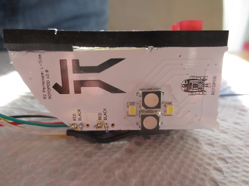
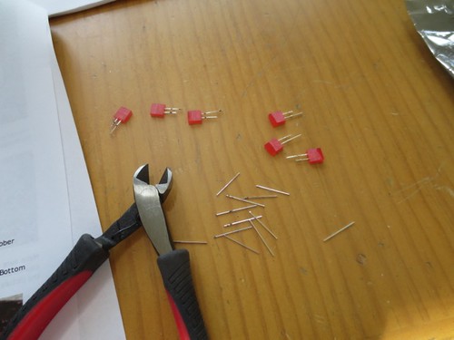
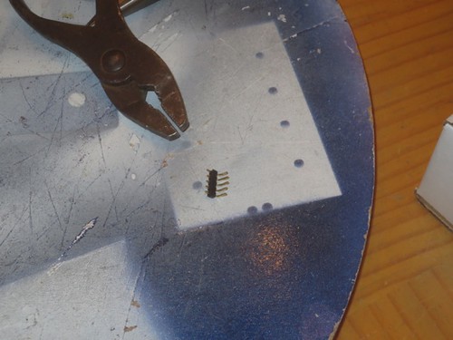
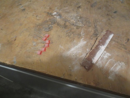
The first order of business was to solder in the six red LEDs that go in the small window in the center-bottom of the main periscope body.
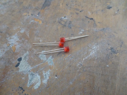
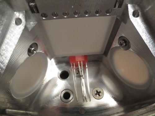
The three LEDs on the left with the hard-to-see black marks on the metal leads are the three LEDs that are stacked horizontally on each other. I know that these have been sanded to fit the hole in the periscope body, so I wanted to make sure I used those three for that purpose.
The black front rubber gasket has tiny holes in it for the LED legs, which needed to be trimmed down before installation and soldering. The gasket helps to align the LEDs properly.
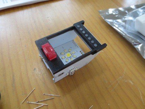
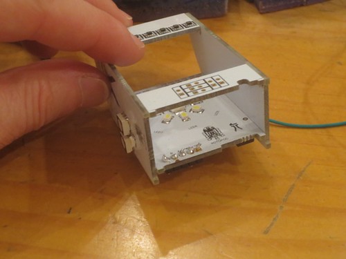
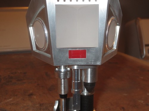
I soldered up the LEDs, trimmed the LED leads down further, and did a test fit in the periscope. Luckily, the LEDs fit through their window perfectly. I managed to sand them properly, and solder them in such that they weren't too crooked.
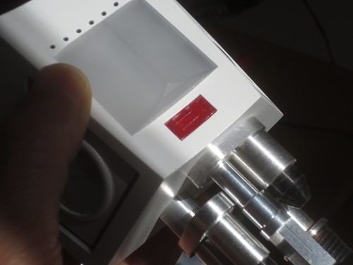
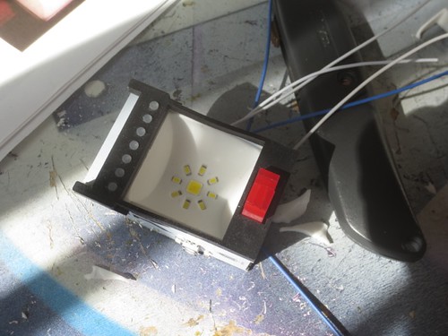
Now the big question, will they light up properly?
Phew, it works.
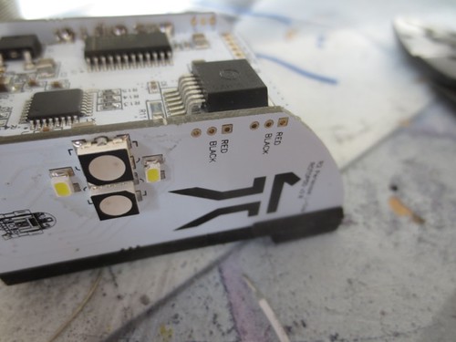
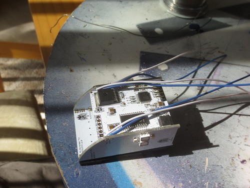
Next, I turned to soldering the wires for the three circular LEDs that are stationed at the rear of the periscope.
There are three pairs of wires for the three LEDs. I soldered each wire up to its respective connection on the main periscope logic board.
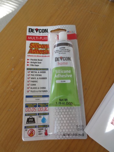
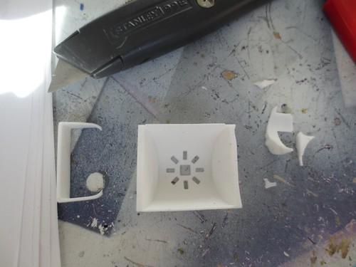
I need to wait until the Devcon Silicone I ordered arrives before I can glue the rear LED gaskets in place, so I wasn't able to test the LEDs yet. Instead, I worked on inserting the white gasket that goes over the main logic board. Per the suggestion in the instructions, I trimmed some of the thicker parts of the rubber gasket.
I then fit the gasket in place.
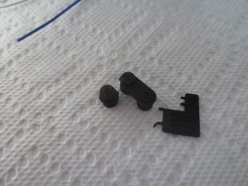
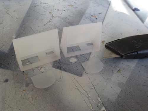
I also took a moment to follow the advice in the instructions, and trimmed the flap on the side LED light diffusers. I'm not ready to install these yet, and they will probably get another minor trim.
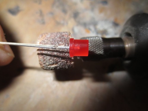
Finally, I trimmed the flange off of the three LEDs with the Dremel drum sander.
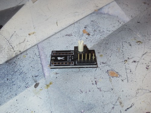
As I'd been suspecting, the 5-pin plastic connector I'd been using to connect the periscope controller board to the main periscope logic board wasn't working out, the wires were too loose in there. So I pulled the wires out.
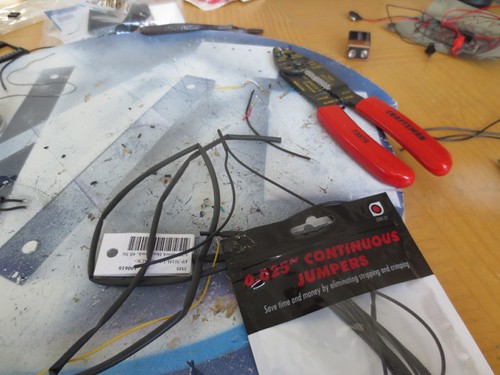
I picked up some "Continuous Jumpers" from my local Fry's Electronics. These have connections on the ends that slip nicely over the connector pins on the two boards. Unfortunately, they are daisy-chained together, so I have to cut them and solder them to the existing wires, but it's not a big deal.
This works better. I have this kind of connection on each end now, and it makes it easier to thread the wires through the wiring hole in the periscope.
Tonight I continued working on the periscope wire-up.
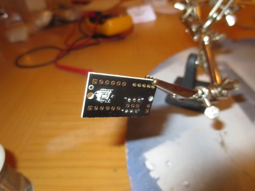
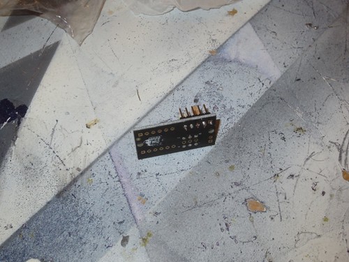
The periscope lighting kit includes pins for soldering to the main periscope board, as well as the controller board. I cut a 5-segment piece of connector, and bent it at a 90 degree angle, in preparation for attachment to the main periscope board.
I soldered the connector in from the inside of the main periscope board.
Rather than go with another 5-pin plastic connector, I picked up some single-pin jumper wires with connectors built in them. I soldered these onto the side of the wires opposite the existing 5-pin plastic connector, and slipped them over the pins on the controller board connector, with the 5-pin plastic connector having been moved to the main periscope logic board.
I still don't think that 5-pin plastic connector is going to cut it, the connections are flaky.
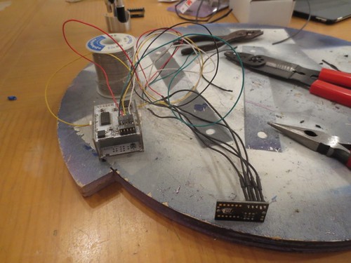
Tonight I spent a little bit of time working on the periscope wiring.
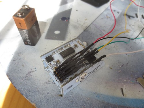
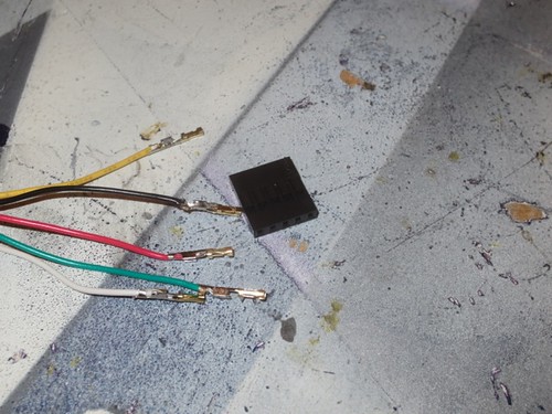
I ran off five different colored lengths of wire. Black and red will supply power, and green, yellow and white will supply the three bits of binary input for selecting mode of operation. These last three wires can be omitted, and the periscope board will default to Mode 0, which nicely rotates through various LED colors and patterns.
For the record, Mode 1 is off, Mode 2 is Obi-Wan mode (blue fades), Mode 3 is Yoda mode (green fades), Mode 4 is Sith mode (red blinking), Mode 5 is Searchlight mode (all LEDs white, including blindingly bright center LED), Mode 6 is Movie mode (white LEDs without the super-bright LED on), and Mode 7 is Sparkle/Seizure mode. The main board is reprogrammable as well.
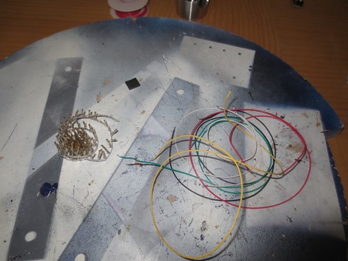
I used some crimp-on connectors, which I then fed and locked into a 5-pin connector shell.
While this kind of works, I have a feeling I'm going to go with a different solution, as the wires wiggle a bit in the 5-pin connector that attaches to the periscope controller board.
I need to figure out how I want to connect the other end of the wires to the main periscope board.
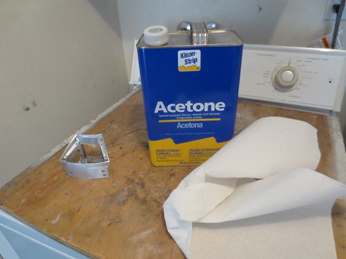
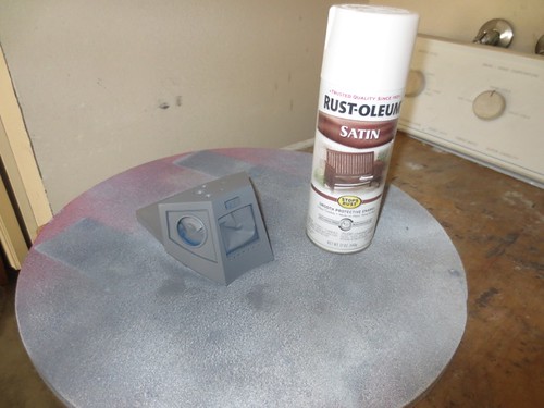
I wiped down the outer surface with acetone to get it nice and clean.
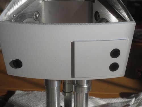
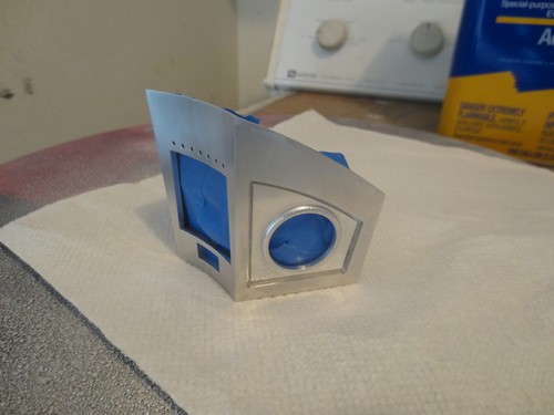
While not necessary, I decided to mask the inside of the periscope body to avoid getting paint all over the place in it.
When I paint with white paint, I usually go with gray primer, so I can distinguish the paint from the primer. I'm using the same Rustoleum Satin White that I used for R2's body. Only one coat this time, though.
This doesn't look very white, but it is. It was indeed a gray day.
I'll let this dry for a while before working with it.
This evening I spent a few minutes working on the Periscope.
The three vertically stacked red LEDs that are visible in the front of the periscope require a little bit of sanding to fit the window through which they are installed, because the LEDs aren't perfectly flat when manufactured. A few minutes with each LED and some sand paper took care of that.
Now things fit nicely.
I spent another minute or two installing the cool tiny rubber light tubes in the front gasket. I love how everything is so customized with this kit.
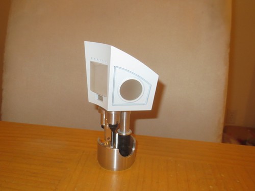
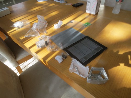
Time to do a little retroactive catching up on work I've been doing on the Periscope. This awesome piece of hardware and software comes courtesy of Michael Wheeler and Doug Dobyns, true artists of their craft.
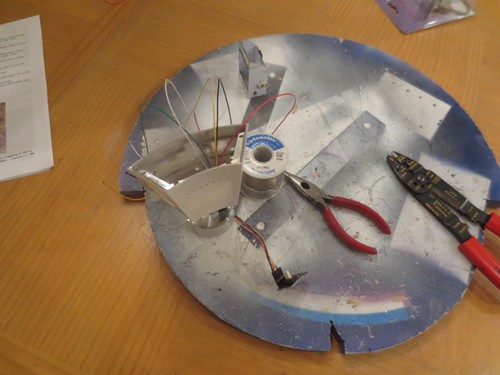
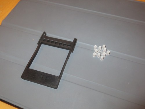
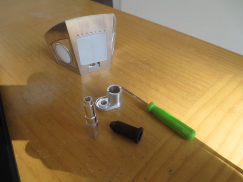
I fired up the iPad, opened the hardware assembly document, and spread the parts out on the table.
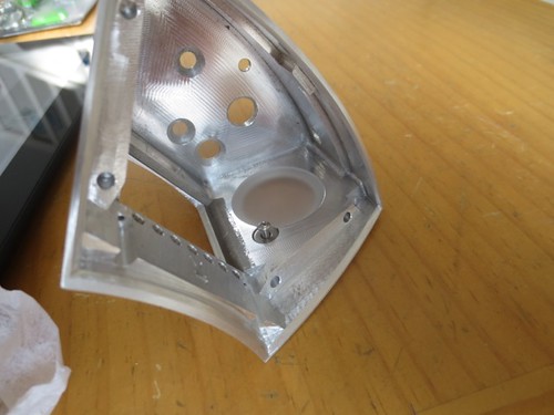
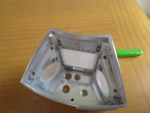
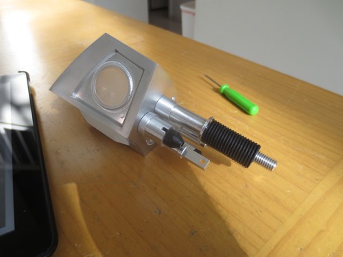
The first step is to install the side lenses, using 2mm screws and washers.
Next, the front prism lens is put in place. It is held down by a pair of 1mm set screws from the inside.
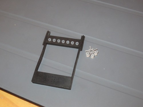
The various shafts and gaskets go together quickly.
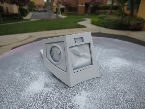
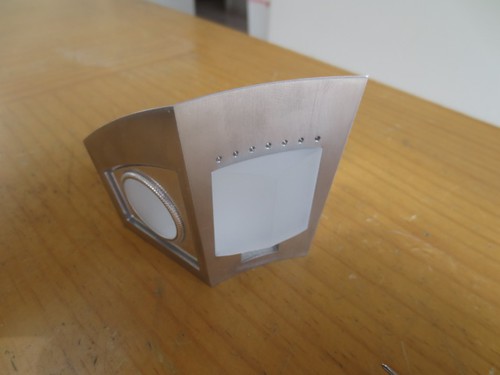
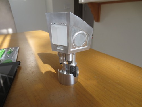
And here it is, the work of art, minus the painting and electronics.
I will need to take this all apart for painting, but I wanted to put it together at least once first to see how it looked, and to ensure I had all the parts, which I do.