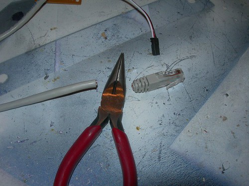
The dome and sound automation controller has a switch that enables or disables the circuit. The switch is of the DPDT variety, and five of the six connections are used. The signals are carried from the circuit to the switch via a category 5 Ethernet cable. Now is the time to chop off the connector end of the cable.
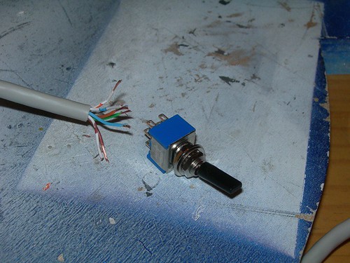
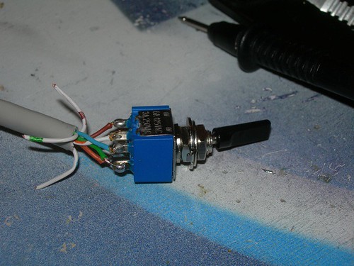
Next, I soldered the five of eight wires to their respective contacts on the switch.
I did a quick test of the circuit's servo-centering abilities, and they worked as expected.
I then started wiring up the snap switches on the dome controller. The Normally Closed contacts are connected with a black wire. I did my usual sloppy job of soldering, but the connection seems to be holding okay.
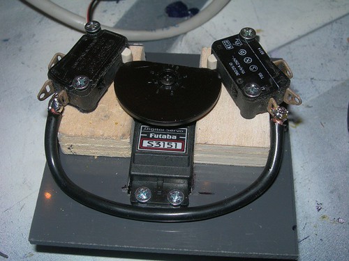
The red wire connects the Normally Open contacts.
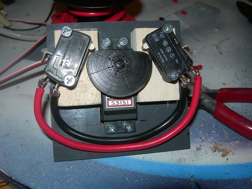
The controller gets its power from the main 12 volt battery. I soldered the wires that will be connected to the power bus to one of the two snap switches. That's all that's required for power.
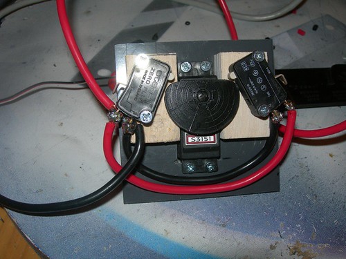
Finally, I loosely attached the motor wires to the Common connection.
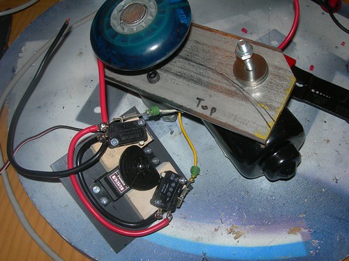
Time to try it out with the 12 volt battery attached! When the servo is in the neutral position, the motor should not move. When either snap switch is actuated, the motor should turn in one direction or the other. I tested the circuit by manually moving the servo disc, but soon I will have the dome and sound automation controller turn it automatically.
I hope to continue the wire up throughout the week.

No comments:
Post a Comment