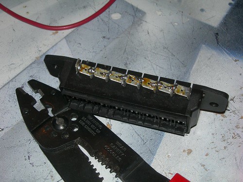
I'm going to use a fuse box to distribute power to the various components. Copying Mike's example, I bent the tabs on one side of the fuse box so that when the tabs are soldered together, one single positive wire from the 12 volt battery supplies the fuse box with power, and each individual 12 volt component will attach to one tab on the other side of the fuse box. The negative battery connection will attach to a bolt that the negative connection of all other components will also attach to. These will replace the positive and negative bus bars that I have on droid #1.

Next, I soldered the tabs together. It looks ugly, but according to the continuity tester, the thing does conduct electricity from end to end. (Why do I have a feeling that when Mike sees this in person, he will be compelled to re-solder it?)
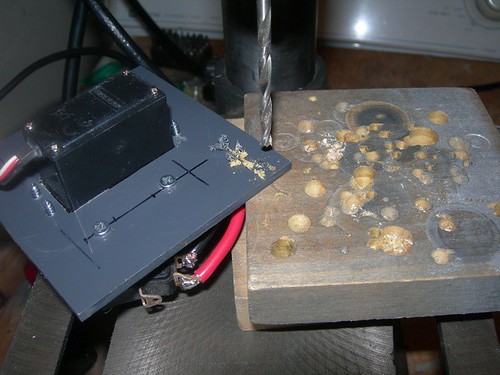
In preparation for attaching the dome controller to the panel, I needed to drill holes though the PVC sheet that hosts the components, since the PVC will ride above the panel.
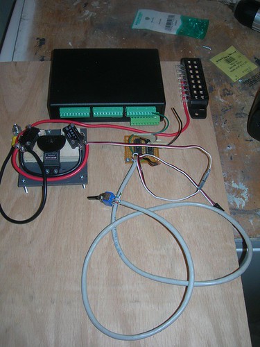
I screwed down the dome controller and circuit, and attached the 1/4" bolt that will act as the negative bus bar. I've also started laying out where I want to place the other various components. The CFSound III is definitely going at the top-center, with the card facing up (obviously). I haven't decided how I want to mount the fuse box yet. I will probably do what Mike did, and have the fuses face straight up. I also need to not forget to add a slightly lower current circuit breaker ahead of the fuse box, so that it will trip first.

No comments:
Post a Comment