The first step is to remove the motor mount bracket from the old drivetrain body.

Next, I measured and marked centerpoints, to translate the motor mount location to the new drivetrain body.

Once I had determined where to mount the bracket on the new drivetrain body, I clamped it down tight and got to drilling.
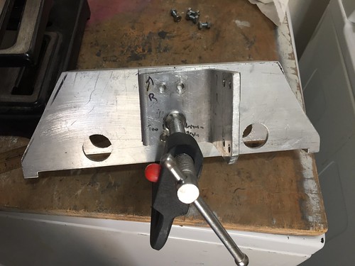

With holes for the motor mount bracket done, it was time to work on the center channel piece. I measured, marked, clamped, punched and drilled. Unlike last night's effort, this time I didn't use the bracket as a template when I did the actual drilling, as the punch left a sufficient location on where to drill.
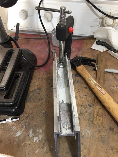
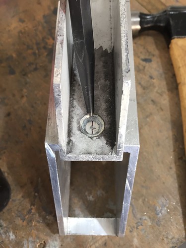

Everything looks nice and centered.

And now the new right drivetrain body has its motor mount and channel holes drilled.

Next I'll work on installing the bearings.

No comments:
Post a Comment