Step one is to take apart the left drivetrain, seen here with the new left drivetrain body, which has holes drilled in it for the bearings.

I removed the motor mount, and found something I didn't even recall, a thin 1/32" shim layer underneath the motor mount, that helps align the gear on the motor with the gear on the axel, so the chain will be straight.


Next, I used my handy ruler with a center finder to mark the center of the top edge of the drivetrain.

After that, I placed the motor mount back onto the drivetrain, so that I could make a centerpoint alignment mark on it. I also measured how far from the top of the drivetrain body that the top of the motor mount bracket resided (about 3mm).

I then used the ruler to locate and mark the center of the top edge of the new drivetrain body.

Next I measured how far from the top to locate the motor mount on the new drivetrain body, and align the motor mount to its centerpoint.

All this alignment is to ensure that the motor fits inside the battery box of the droid, and to hopefully be able to recycle the same chain by keeping the distance of the motor and the drive gear the same distance. This second goal is quite touchy, even a millimeter or so difference may lead to the need to either build new chain, or change how the motor needs to be shimmed from the motor mount.
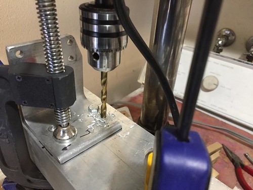
I clamped everything super tight and started drilling the four holes, using the motor mount itself as a template. After each hole was drilled, I dropped bolt into it. I think the clamp was holding everything so tightly, the motor mount wasn't going to wander, but this adds a degree of confidence that all the holes will line up.
Once the holes for the motor mount were drilled, it was time to turn my attention to the top channel piece. It is held onto the old drivetrain body by a couple of short 1/4" diameter bolts and nuts.

I measured and marked center points on the new drivetrain body, to ensure that the channel would be centered on it.

I removed the channel piece from the old drivetrain body and centered it on the new one, and used my trusty punch to indent the point at which to drill the first hole.
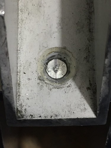
As with the motor mount, I tightly clamped down the channel piece to the new drivetrain body, and drilled.

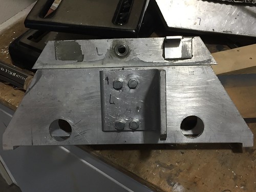
I repeated the process for the other hole, and temporarily fitted the motor mount and channel piece on the new drivetrain body.
Still lots of work to do. First up, replaying the whole process on the right drivetrain, and then I'll need to press-fit the bearings and start checking if the existing chain from the motor to the drive gear will fit (I'm expecting it probably won't). I should be able to use the chain on the other side of the drivetrain body if I don't mess up, since there is an idler gear that takes up slack on the chain, and it can be placed anywhere it's needed. (That will be clearer when I get to that step.)


No comments:
Post a Comment