Sometimes I get a little too creative in my setups.

This was mostly a repetitive process. First, I'd grab the segment of PVC that I needed to secure to the dome.
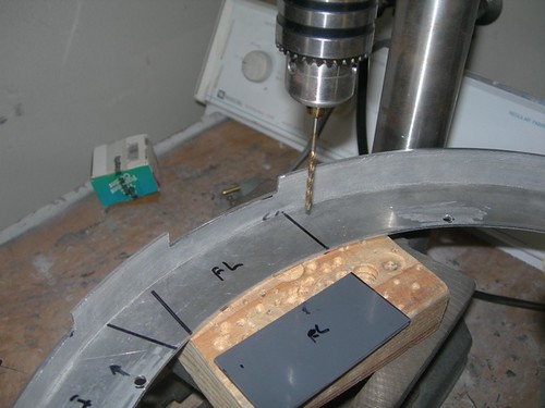
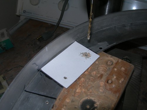
Next, I'd hold it in place on the dome ring, and drill a hole through the PVC and through the ring in one shot.
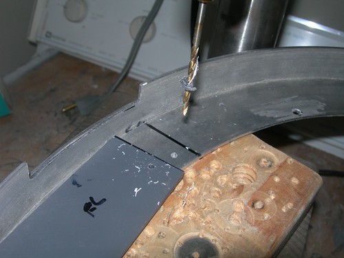
Finally, I'd secure the PVC with a screw and nut on the first hole, and drill the second hole, ensuring that the holes would match up.

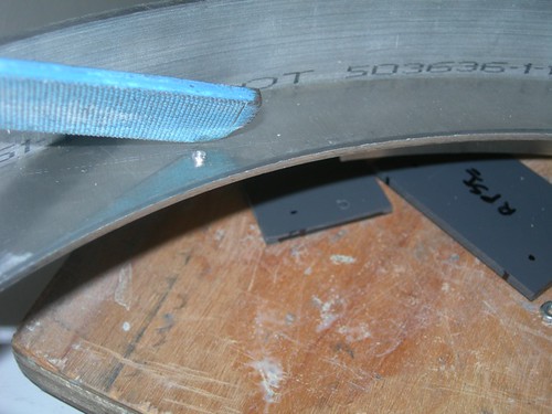
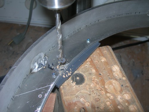
The drilling process leaves small aluminum volcanoes on the underside that I filed down.
I repeated this process for all the PVC bases, and for the battery holders.

The front PSI base piece covers up the hole for the front screw for the Rockler bearing, so that needs to be drilled from the underside with a larger bit.

For the J.E.D.I. DC/DC power supply and display controller, I decided to recycle a mounting plate that I did not end up using for droid #1. I'm not sure this actually saved me time, as using it presented its own challenges.
First, I could not use the base directly as a template for drilling the dome ring, since another large piece of PVC is glued to the base perpendicularly. Instead, I traced the outline and marked where the holes should go on a piece of card stock and used that as a template instead
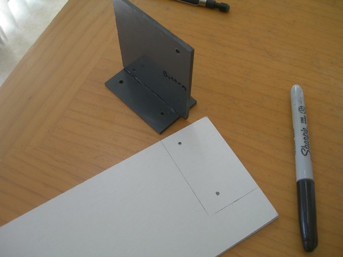
There were already two holes in the vertical piece of PVC that happened to match the holes on the DC/DC power supply board, but I needed to drill mounting holes to match those on the display controller board.
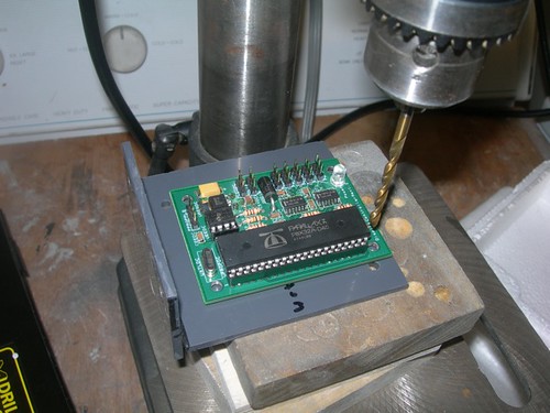
The plan was to mount the DC/DC power supply board on one side, and the display controller board on the other. Things were going well until I tried fitting the assembly on the dome ring. At that point I realized that there wasn't enough room for the connectors on the 3-pin headers. (The nylon screws could be cut short as needed.)

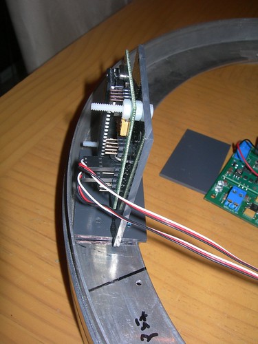
I saw that if I rotated the assembly around, I could get everything to fit. So I flipped the PVC assembly around, and used the holes in the dome ring as a guide for drilling the PVC base.

That's better.
I think I'm done drilling the dome ring.

I still need to build up the rest of the PVC harnesses that will secure the front logics and PSIs.

2 comments:
Isn't it something that with a second build, you PLAN for all these things rather than wing it during the build??
And yet, I still goof up from time to time. :)
Post a Comment