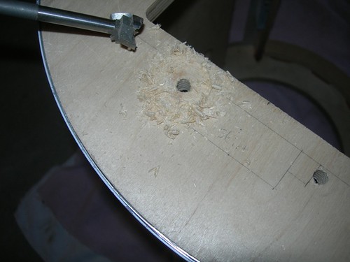
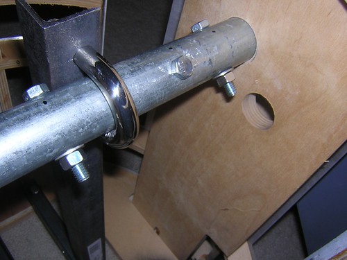
I finally got my grubby hands on the Bad Dog drill bits that my friend Kelvin owns. I wanted to use these to slightly countersink the t-nuts that go into the underside of the frame; the reason being, I don't want the t-nuts to interfere with the skirt. These t-nuts are used for the bolts that secure the center leg rails to the bottom of the inside of the frame.
With the centerpoint already drilled out, it was difficult to keep the bit centered, but that wasn't a priority. I drilled just deep enough to allow the t-nut to clear the bottom of the frame.
A little torquing with the socket wrench, and all four t-nuts are in place. I will either use washers on the rails to shim the bolts higher, or I will cut the bolts down so they don't protrude beyond the bottom of the frame. Or I'll find shorter bolts. Or something.
Monday, August 31, 2009
Sunday, August 30, 2009
Started Working on Front Vent Harness
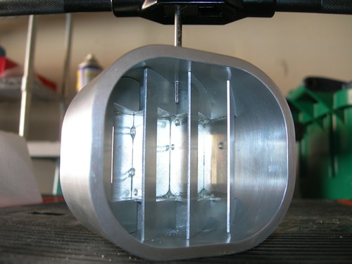
Today I got started on the front vent harness assembly.
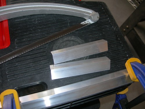
The first thing I did was cut a couple of 4.25" segments from some aluminum angle rails, that are 3/4" on each side and 1/16" thick.
I realized that I needed to file the paint from the inner perimeter of the skin piece that goes around the vents, in order to get the vent surrounds to fit through, so I spend several minutes with a half-round file doing that. I took care to always pull the file from the front face of the piece through the back, never pushing out through the front. This helps avoid chipping the paint on the front face.
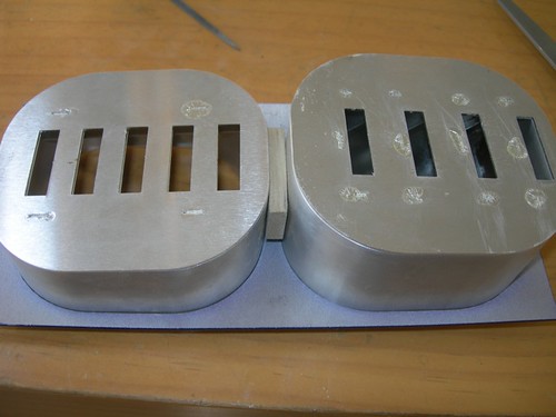
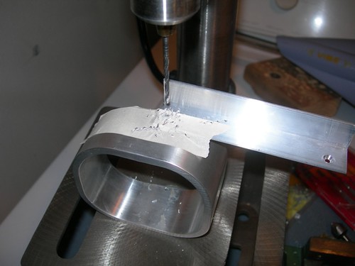
Using a 1/4" MDF rectangle to separate the surrounds, I fitted them in the skin piece, and then used masking tape to tape the segments of bar in place.
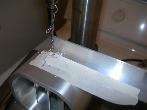
Next, I took the work to the drill press, where I drilled for 4-40 screw holes to be tapped.
I got busy tappin'.
I went back and widened the hole in the rail so that a 4-40 screw could pass through, and countersunk.
With the top vent drilled and ready to go, I taped the aluminum rail to the bottom vent and repeated the process. Note that it is very important to lay the two surrounds face down when determining where to attach the rail. Each surround is different, and they should be aligned along their front faces, not along their backs.
Done for now. The harness seems to be ready to go, but I will likely need to do some very minor hacking on the frame to get it to fit.
Friday, August 28, 2009
Installed Octagon Ports
Tonight I worked on installing the octagon ports.
First, I cut a 1.25" strip of 1/8" MDF, that will serve as the mounting pieces.
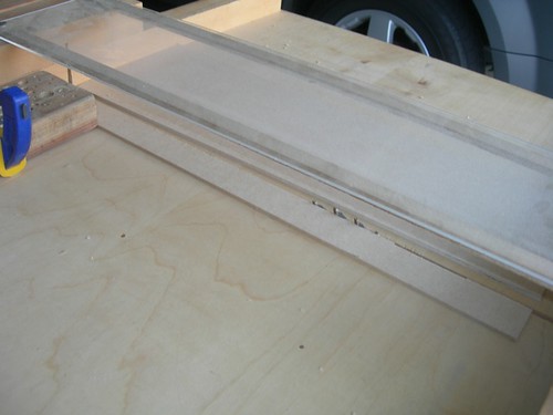
Next, i measured how tall each strip should be to reach from the rib above the octagon port, to just below the middle of the octagon port.
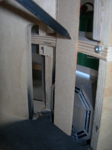
I prepared to drill the mounting holes into the back of the octagon port. The middle part of the octagon port is 0.60" tall, I set the drill press to drill 3/8" (0.375") deep, to be on the safe side.
I used strapping tape to secure the MDF holder, and drilled through the MDF and octagon port as a pair.
I also used the MDF as a template for drilling the holes in the MDF holder for the other octagon port.
I tapped the holes in the back of the octagon port for 4-40 screws.
Next, I measured and marked where to drill the mounting hole for the MDF holder to hang from the rib above the octagon port, and also colored the area black that can be seen through the ribbing of the octagon port.
Finally, it came time to mount the part.
Hey, the top of the octagon port isn't sitting flush with the skins!
Okay, no problem. I'll add a 1/8" MDF shim layer.
Hey, the bottom part of the port isn't fitting all that snug either!
Okay no problem, I'll jam something behind the lower part of the octagon port. About 1/16" of MDF should do. This is a temporary solution, I'll probably glue a small piece of styrene to the back of the MDF holder.
Okay, now things are looking reasonably good.
I'll probably work on installing the front vents next. That setup is a bit more elaborate.
First, I cut a 1.25" strip of 1/8" MDF, that will serve as the mounting pieces.
Next, i measured how tall each strip should be to reach from the rib above the octagon port, to just below the middle of the octagon port.
I prepared to drill the mounting holes into the back of the octagon port. The middle part of the octagon port is 0.60" tall, I set the drill press to drill 3/8" (0.375") deep, to be on the safe side.
I used strapping tape to secure the MDF holder, and drilled through the MDF and octagon port as a pair.
I also used the MDF as a template for drilling the holes in the MDF holder for the other octagon port.
I tapped the holes in the back of the octagon port for 4-40 screws.
Next, I measured and marked where to drill the mounting hole for the MDF holder to hang from the rib above the octagon port, and also colored the area black that can be seen through the ribbing of the octagon port.
Finally, it came time to mount the part.
Hey, the top of the octagon port isn't sitting flush with the skins!
Okay, no problem. I'll add a 1/8" MDF shim layer.
Hey, the bottom part of the port isn't fitting all that snug either!
Okay no problem, I'll jam something behind the lower part of the octagon port. About 1/16" of MDF should do. This is a temporary solution, I'll probably glue a small piece of styrene to the back of the MDF holder.
Okay, now things are looking reasonably good.
I'll probably work on installing the front vents next. That setup is a bit more elaborate.
Wednesday, August 26, 2009
Installed Coin Slots and Front Power Coupler
This evening I worked on installing the coin slots (which I haven't painted yet), and the front power coupler (which I have painted). First up, the coin slots.
I needed to trim about 1/8" off the top of the coin slots, to avoid having the top of the part bump into the rib above it. I did this using the Dremel with the cutoff wheel.
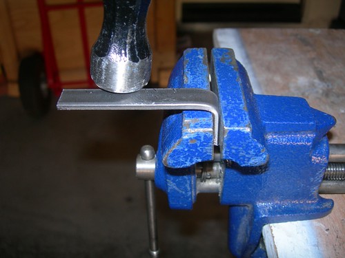
Next, I cut a couple of 3.5" segments of bar, that I hammered into an 'S' shape to help hold the coin returns in place.
I marked and drilled a hole for a 3/4" long #4 wood screw that will secure the bar in place.
For droid #1 I have one of these bars, I decided to go with a pair of them for droid #2. Thecretins little angels sometimes like to press the coin slots in, so this should help keep them in place.
Next up, the front power coupler. As with droid #1, I stayed with the metal bars again. I cut a couple of segments, roughly 1.25" to 1.50" long, and marked and drilled the holes for a 3/4" #4 wood screw, just like for the coin slots.
With the two bars screwed down, the power coupler is secure.
I might work on installing the octagon ports next, but I need to decide exactly how I'll deal with the aluminum version I'm using on droid #2. I'll likely do something similar to what I did for droid #1, and drill a couple of holes for screws in the back and attach some sort of paddle to the back of the octagon port and to the rib above it. We shall see.
I needed to trim about 1/8" off the top of the coin slots, to avoid having the top of the part bump into the rib above it. I did this using the Dremel with the cutoff wheel.
Next, I cut a couple of 3.5" segments of bar, that I hammered into an 'S' shape to help hold the coin returns in place.
I marked and drilled a hole for a 3/4" long #4 wood screw that will secure the bar in place.
For droid #1 I have one of these bars, I decided to go with a pair of them for droid #2. The
Next up, the front power coupler. As with droid #1, I stayed with the metal bars again. I cut a couple of segments, roughly 1.25" to 1.50" long, and marked and drilled the holes for a 3/4" #4 wood screw, just like for the coin slots.
With the two bars screwed down, the power coupler is secure.
I might work on installing the octagon ports next, but I need to decide exactly how I'll deal with the aluminum version I'm using on droid #2. I'll likely do something similar to what I did for droid #1, and drill a couple of holes for screws in the back and attach some sort of paddle to the back of the octagon port and to the rib above it. We shall see.
Sunday, August 23, 2009
Widened Dome Ring Holes for Rockler Bearing
Once again, doing the bare minimum...
The dome ring was rubbing up against the screws that hold it onto the Rockler bearing, enough so that when I tried to fit the ring to the bearing, the ring had a tendency to get stuck. The back three screws went through the holes in the dome ring, but the front three didn't fit so well.
I marked the holes that required a small bit of widening, using a Sharpie to locate where a little extra material should be drilled out.
I used a hand drill to grind the holes, making them just a bit larger.
A few minutes later, I had a good fit between the ring and the bearing. Not too loose, not too tight.
As happens from time to time, I couldn't help myself, and I did a loose fit of a bunch of junk on the droid. All the panels are just held on by gravity, as are most of the other parts. Don't sneeze. (I've since taken everything off the droid.)
Saturday, August 22, 2009
Started Sanding Eye to Dome Profile
Today I continued working on the resin eye, this time beginning to fit it to the dome profile.
First I blindfolded R2 with masking tape, to protect the area from scratches as I worked.
Then, it was mainly a matter of placing a half sheet of 150 grit sand paper sandwiched between the dome and the eye, and sanding down the edges of the back of the eye. I was careful to keep the sandpaper taut against the dome, so as not to sand creases into the edges of the eye (which I almost did on droid #1).
Once things looked pretty close, I removed the tape and checked the fit against the dome.
The top and bottom edges are nice and snug, but the left and right edges could use just a little more work.
Mike Senna once gave me some particularly good advice, along the lines of, "Sometimes, you gotta know when to put down the tools and call it a day." This point in the day was just about that time.
However, I decided to Dremel out some material from the back of the eye to help bring the lens further forward. I made a mess of things in the back of the eye, but I don't think I've done any real damage. It just looks sloppy, because it is.
Friday, August 21, 2009
Started Working on Eye
Well, it just might be time to resume dome work. The first thing I ever did for droid #2 was cut the panels out on the dome and have them painted, so it's about time.
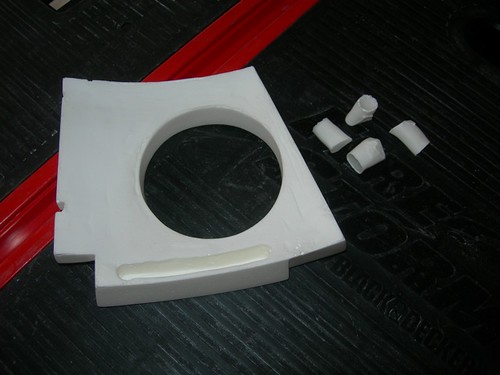
Rather than work on the dome itself, I'm starting with the resin eye. The first thing to do is trim the four legs off the back. I used the Dremel with the cutoff wheel attachment to remove most of the legs.
I used the drum sander attachment to remove most of the remaining material. I also removed some material from the back of the eye in general, in order to help ensure that it will be the perimeter of the eye that sits flush against the dome.
I finished up by hand sanding the remaining nubs off the four corners.
Next, I will tape some sand paper to the outer dome, and sand the eye against the dome itself, to ensure the correct profile, and a flush fit. Hopefully that won't take forever like it did with droid #1.
Monday, August 17, 2009
Pipe Bolt Problem Resolved
Being wrong all the time occasionally has its advantages.
When I drilled the 5/8" holes to lock the leg pipes together, after I inserted the 5/8" bolts through the holes there was enough wiggle in the legs that I thought there was no way that locking everything down tight with washers and nuts would sufficiently reduce the wiggle between the leg pipes. Fortunately, I was wrong.
I needed to pick up washers at Home Depot, so couldn't test this until tonight. I cranked down on the nuts with a wrench.
After tightening all five sets of bolts, washers and nuts, the legs their pipes are indeed locked together. As far as I can tell, this will work. Yea!
Saturday, August 15, 2009
Discovery Science Center Robotics Event
Today R2 joined several other droids and many members of the 501st and Rebel Legion, for the Discovery Science Center's Robotics exhibition that is taking place in Santa Ana, CA.
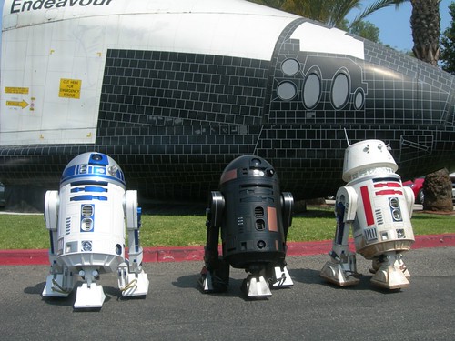
Along with my R2-D2, Chris Romines brought R2-A1, and Vince Sanchez brought R5-D4. Later, Max Cervantes brought RT-R2 and Mike Senna joined as a Stormtrooper.
As usual, the droids drew kids like flies to gasoline.
Michael McMaster came down for the day from Central California to tape the goings-on.
Watch out for those Jawas!
We had quite an impressive array of characters!
The Orange County Sheriff's Department also came with one of their bomb squad robots. These babies cost $200,000 apiece. Naturally, we studied the motors and batteries. Note Senna studying the underbelly. Boy or girl?
Mike put his armor and weaponry to good use.
It's been a while since R2 has had a chance to pose for pictures with his friends, he had a fun day.
Subscribe to:
Posts (Atom)