Saturday, September 12, 2009

Glued Down Utility Arm Outer Skin Panels

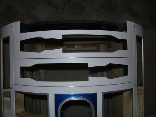
It was a busy non-droid building day, but I managed to squeeze in just enough time to prep and glue down the outer skin panels that go around the utility arms.

The first step is to lightly sand the inner skins and the backs of the outer skin panels to rough them up, remove the layer of oxidation on the aluminum, and in the case of the outer skin panels, remove some of the white spray paint that misted onto the backs of the pieces. I used 220 grit sand paper for this job.
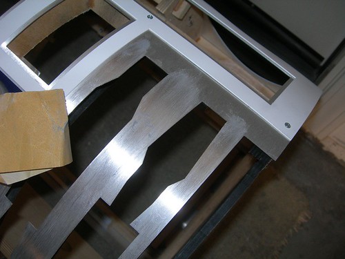


Once I was done sanding, I cleaned everything up with acetone, taking care not to accidentally touch the painted skins with the acetone. Shiny!
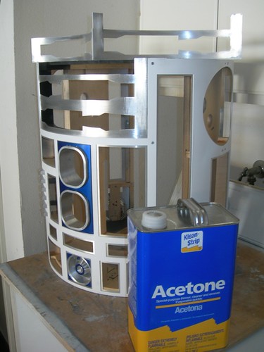


Next, I ran a thin bead of silicone on the back of the lower utility arm panel.
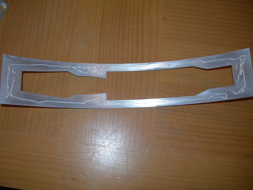


After I spread it around with my finger, I affixed the panel to the inner skins in place.
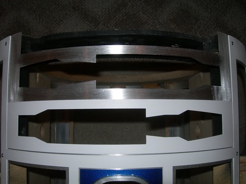


I repeated the process for the upper panel.
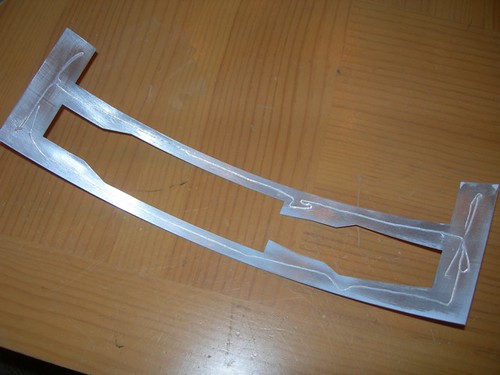


After spreading the silicone around with my finger, it's hard to see the silicone, but it's there.


The second piece is in place, and I'll let this dry overnight. Hopefully it will stay where it belongs and I can move forward with the utility arm installation.
Thursday, September 10, 2009

Started Working on Utility Arms

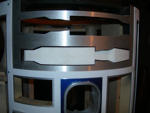
Time to fill some more holes in the body. This time, the utility arms.

I had strongly considered building a sturdy harness for the arms on droid #2, but in the end, I decided to build a heartier version of what I have for droid #1. It turns out I didn't copy Mike Senna exactly with droid #1. I used a lot of 1/8" material, this time things will be beefier.

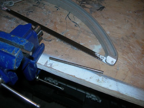
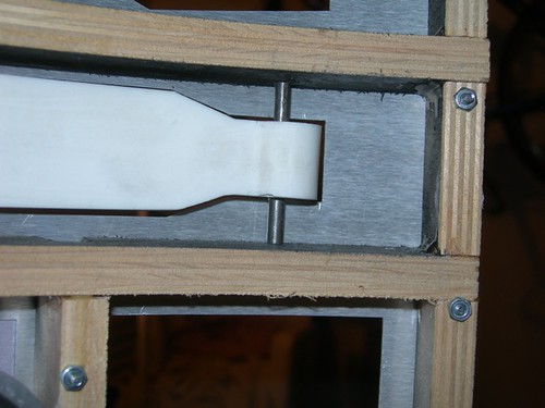
The first example is the rod I'm using as the pivots for the arms. On droid #1 this is 1/8" brass stock, for droid #2 it is 3/16" steel. I cut a segment that should be provide enough length for both arms.


I took the segment, and marked the length required for the bottom arm.


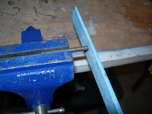
I went a tiny bit long on the cut, and filed it to size.


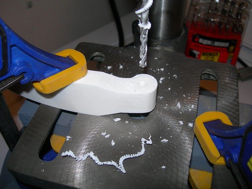
Time to drill the 3/16" hole in the resin arms.


Using just friction for the time being, the fit is very snug, but that's what I want at this point. I may sand or file the segment of rod just a little more, later.


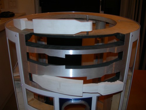
Next, I needed to address the geometrical problem of having the arms swing open without having them hit the skins. This is not a blueprint error or manufacturing error with the arms, it's just the way three-dimensional objects interact.

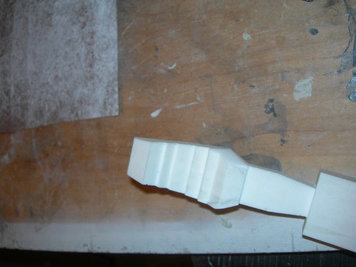
My solution is to file some material from the sides and back of the resin arm, leaving the front face fully intact. Here I've almost finished one half of one arm. I'll try to get better before/after pictures later.


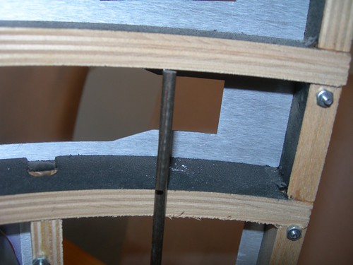
If the bottom arm is placed perfectly (which is a challenge at the moment), then I can get it to swing open without hitting the skins. I may have to file off a little more material to provide a wider tolerance for arm placement (we're talking probably +/1 a millimeter or less).


At this point, I should attach the portion of the outer skin that goes around the arms before going much further, so I can make sure the arms don't catch on the outer skins as well. I plan to use my friend/enemy silicone for that. I also plan to reinforce the MDF above the top utility arm with plywood, as the arms need something beefier to mount to.

Sunday, September 06, 2009

Installed Front Vents

Today I had a little time to install the front vent housing assembly on the frame.

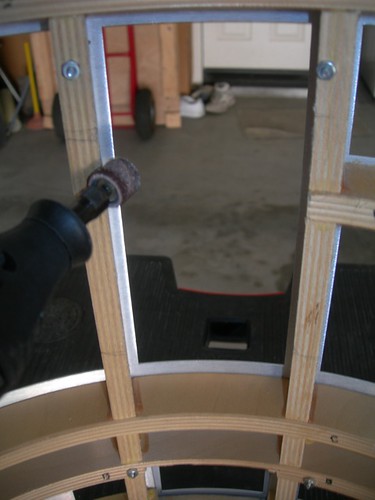
The fit was a bit too snug, so I needed to remove just a little material from the adjacent vertical ribs, using the Dremel drum sander.


There is a rib to the right of the assembly that interferes a bit with the right rail, so I marked where to cut a small portion of the rail, to make a slot for this rib, and then I did the cutting.


I reinstalled the harness on the frame, and determined where to drill the mounting holes.


Then, over to the drill press to drill the holes in the rails.


I used four #4x3//4" wood screws to mount the harness onto the frame.


Things are looking reasonably good. I may or may not make very minor adjustments in the future, but I think I could live with this.

Monday, August 31, 2009

Installed Center Rail T-Nuts in Frame

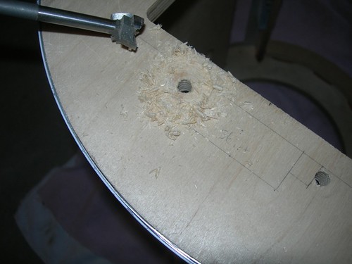
I finally got my grubby hands on the Bad Dog drill bits that my friend Kelvin owns. I wanted to use these to slightly countersink the t-nuts that go into the underside of the frame; the reason being, I don't want the t-nuts to interfere with the skirt. These t-nuts are used for the bolts that secure the center leg rails to the bottom of the inside of the frame.


With the centerpoint already drilled out, it was difficult to keep the bit centered, but that wasn't a priority. I drilled just deep enough to allow the t-nut to clear the bottom of the frame.


A little torquing with the socket wrench, and all four t-nuts are in place. I will either use washers on the rails to shim the bolts higher, or I will cut the bolts down so they don't protrude beyond the bottom of the frame. Or I'll find shorter bolts. Or something.

Sunday, August 30, 2009

Started Working on Front Vent Harness

Today I got started on the front vent harness assembly.

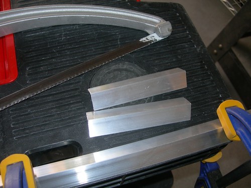
The first thing I did was cut a couple of 4.25" segments from some aluminum angle rails, that are 3/4" on each side and 1/16" thick.


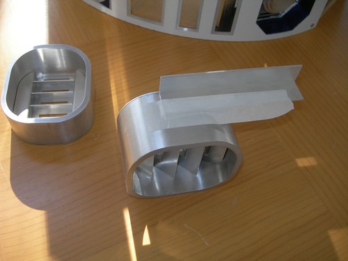
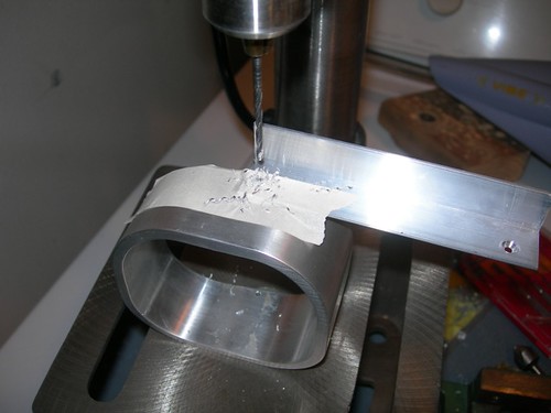
I realized that I needed to file the paint from the inner perimeter of the skin piece that goes around the vents, in order to get the vent surrounds to fit through, so I spend several minutes with a half-round file doing that. I took care to always pull the file from the front face of the piece through the back, never pushing out through the front. This helps avoid chipping the paint on the front face.


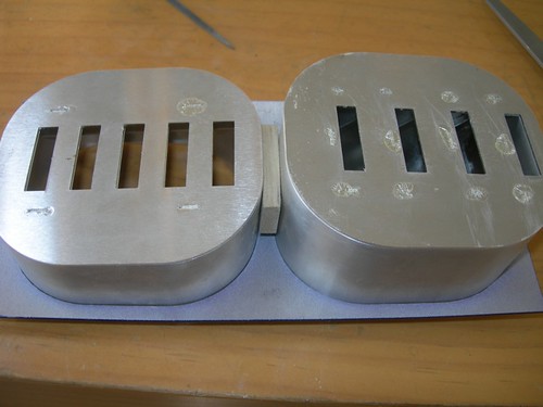
Using a 1/4" MDF rectangle to separate the surrounds, I fitted them in the skin piece, and then used masking tape to tape the segments of bar in place.


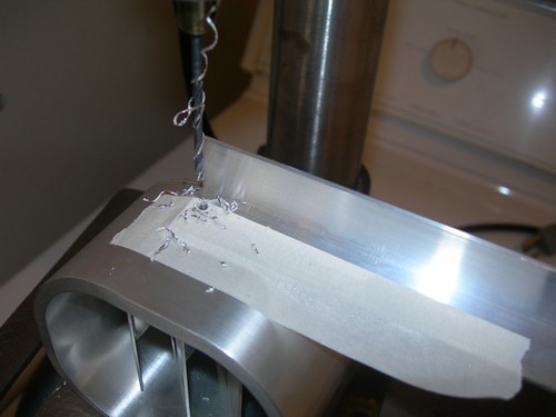
Next, I took the work to the drill press, where I drilled for 4-40 screw holes to be tapped.


I got busy tappin'.


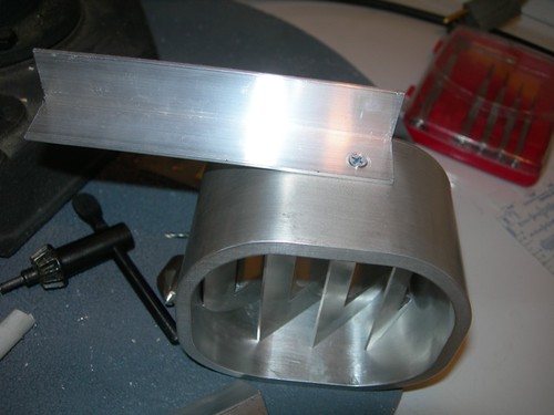
I went back and widened the hole in the rail so that a 4-40 screw could pass through, and countersunk.


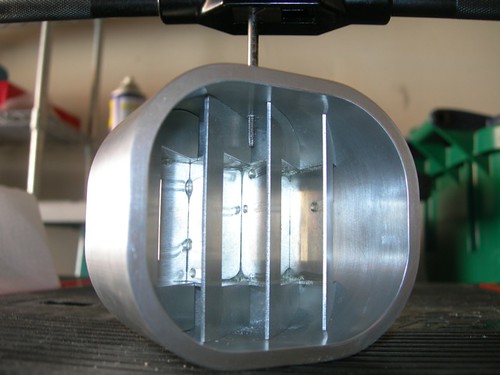
With the top vent drilled and ready to go, I taped the aluminum rail to the bottom vent and repeated the process. Note that it is very important to lay the two surrounds face down when determining where to attach the rail. Each surround is different, and they should be aligned along their front faces, not along their backs.


Done for now. The harness seems to be ready to go, but I will likely need to do some very minor hacking on the frame to get it to fit.

Friday, August 28, 2009

Installed Octagon Ports

Tonight I worked on installing the octagon ports.

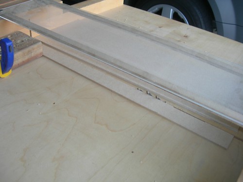
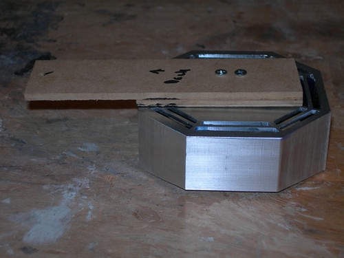
First, I cut a 1.25" strip of 1/8" MDF, that will serve as the mounting pieces.


Next, i measured how tall each strip should be to reach from the rib above the octagon port, to just below the middle of the octagon port.


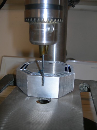
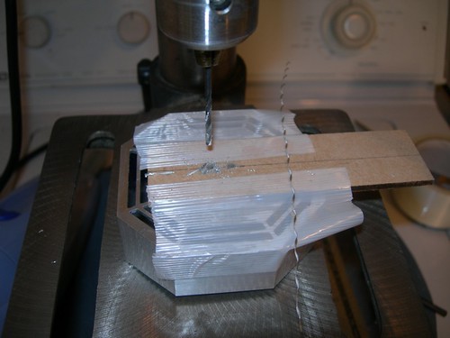
I prepared to drill the mounting holes into the back of the octagon port. The middle part of the octagon port is 0.60" tall, I set the drill press to drill 3/8" (0.375") deep, to be on the safe side.


I used strapping tape to secure the MDF holder, and drilled through the MDF and octagon port as a pair.


I also used the MDF as a template for drilling the holes in the MDF holder for the other octagon port.


I tapped the holes in the back of the octagon port for 4-40 screws.


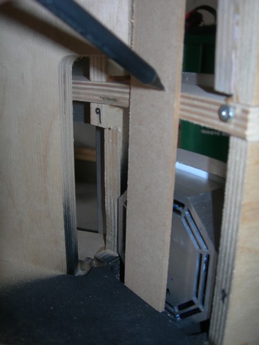
Next, I measured and marked where to drill the mounting hole for the MDF holder to hang from the rib above the octagon port, and also colored the area black that can be seen through the ribbing of the octagon port.


Finally, it came time to mount the part.

Hey, the top of the octagon port isn't sitting flush with the skins!


Okay, no problem. I'll add a 1/8" MDF shim layer.


Hey, the bottom part of the port isn't fitting all that snug either!

Okay no problem, I'll jam something behind the lower part of the octagon port. About 1/16" of MDF should do. This is a temporary solution, I'll probably glue a small piece of styrene to the back of the MDF holder.


Okay, now things are looking reasonably good.


I'll probably work on installing the front vents next. That setup is a bit more elaborate.

Wednesday, August 26, 2009

Installed Coin Slots and Front Power Coupler

This evening I worked on installing the coin slots (which I haven't painted yet), and the front power coupler (which I have painted). First up, the coin slots.

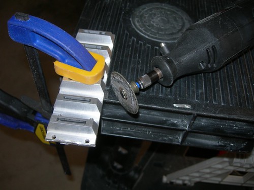
I needed to trim about 1/8" off the top of the coin slots, to avoid having the top of the part bump into the rib above it. I did this using the Dremel with the cutoff wheel.


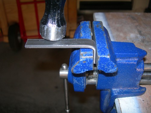
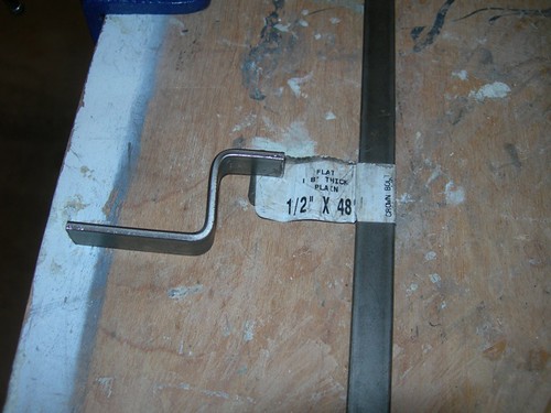
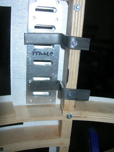
Next, I cut a couple of 3.5" segments of bar, that I hammered into an 'S' shape to help hold the coin returns in place.


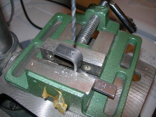
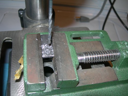
I marked and drilled a hole for a 3/4" long #4 wood screw that will secure the bar in place.


For droid #1 I have one of these bars, I decided to go with a pair of them for droid #2. The cretins little angels sometimes like to press the coin slots in, so this should help keep them in place.


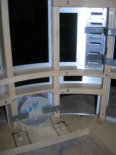
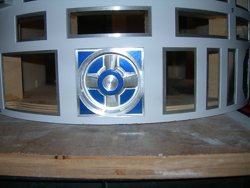
Next up, the front power coupler. As with droid #1, I stayed with the metal bars again. I cut a couple of segments, roughly 1.25" to 1.50" long, and marked and drilled the holes for a 3/4" #4 wood screw, just like for the coin slots.
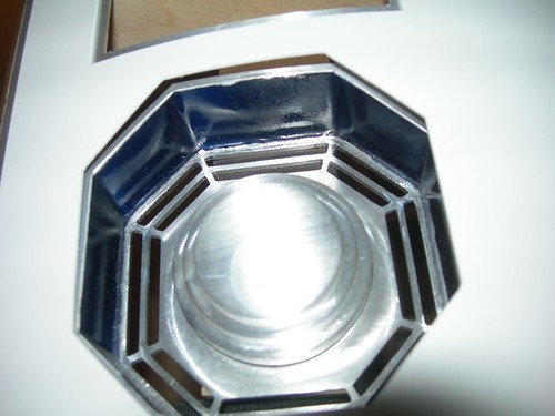


With the two bars screwed down, the power coupler is secure.


I might work on installing the octagon ports next, but I need to decide exactly how I'll deal with the aluminum version I'm using on droid #2. I'll likely do something similar to what I did for droid #1, and drill a couple of holes for screws in the back and attach some sort of paddle to the back of the octagon port and to the rib above it. We shall see.