

Next, time to wire up the solid state relay. I located where I wanted to place the relay and its mounting bracket on the board.

And then I got to wiring.
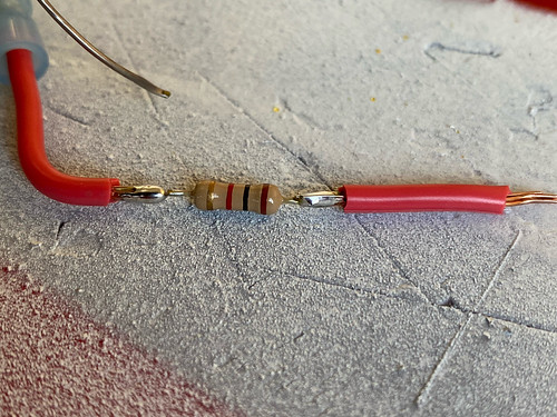
I'm getting a bit fancy with the SSR. I want it to be normally closed (allowing current to the speed controller), and if I hit a button on the transmitter, then I want the circuit to be open, killing power to the speed controller. This means that the positive input to the SSR input needs to normally be at +12 volts, so I use a pull-up resister to +12 volts to achieve that. When I want to kill the power to the speed controller, pressing a button on the transmitter grounds that input, turning off the SSR.
Once everything was wired up, I applied some thermal paste to the SSR side of the mounting bracket. I think that's done for now.

That wiring is still a mess. I will tackle that next.

No comments:
Post a Comment