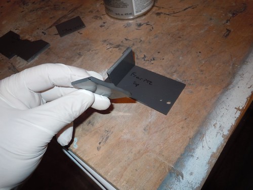
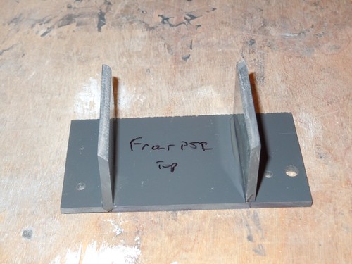
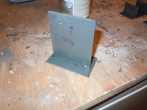
I started with gluing the PSI holder for front PSI, and the DC/DC converter & Display Controller board holder.
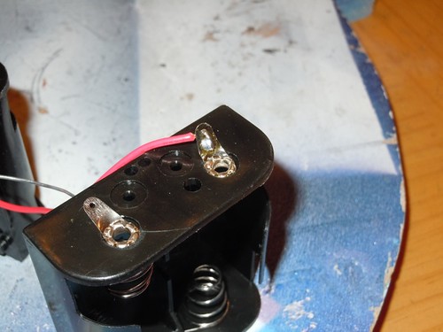
Next, I worked on the power distribution system. Where better to start than the on/off switch?

There won't be much activity without batteries, so those got wired up next.
I then added the 9 volt and 5 volt power distribution strips, and the DC/DC converter and Display Controller. The batteries feed into the 9 volt power distribution strip, which feeds the DC/DC converter. The 9 volt board can also power other electronics, such as the PSI circuits I recently assembled. The DC/DC converter sends 5 volts to the 5 volt power distribution strip, which feeds the various JEDI electronic components. I gave a quick test with the rear logics, and all is well.

Still a lot to do.

No comments:
Post a Comment