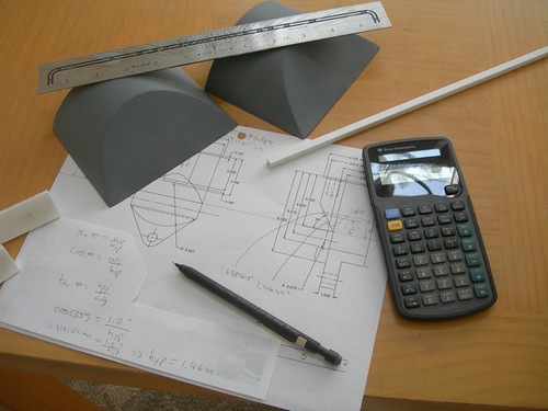
With a little trigonometry, I determined that the bottom of the slot starts at 1.46" above the bottom of the sloped part of the ankle, while the top of the slot ends at 1.69" from the bottom of the sloped part of the ankle. I measured and marked the outline for the slots.
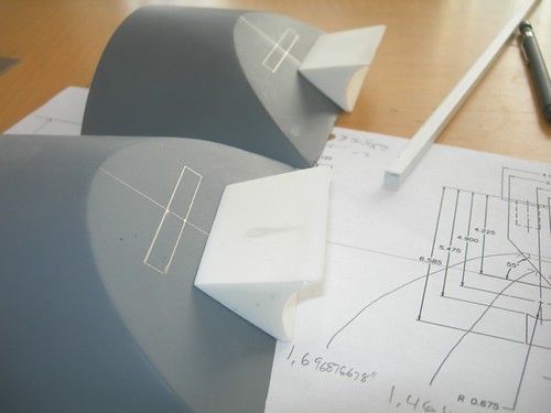
For droid #1, I used a router bit to cut the slot into the ankle. This time, I used the Dremel with the cutoff wheel.
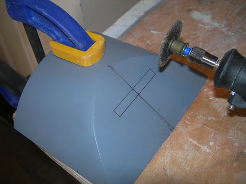
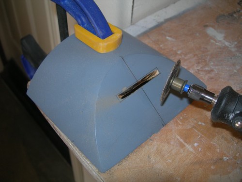
What the Dremel didn't get, I managed to clean up with an assortment of files. This was a bit tedious and time-consuming, but such is droid building.
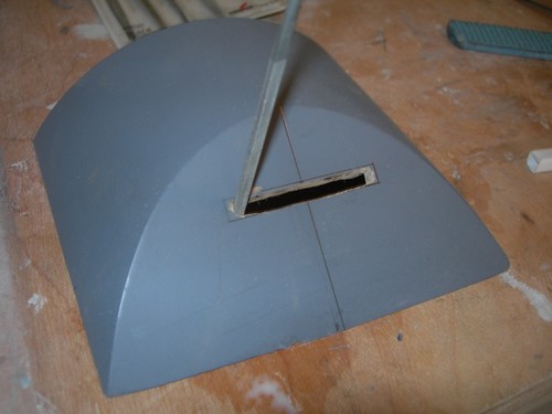
I increased the height of the slots slightly taller than to spec, as I am going to insert some styrene channel that Alan Wolfson kindly provided at R2LA VI. The Kenny Baker R2 shows that slot in the ankle is backed by a right angle, rather than a flat cover, hence the square channel. Alan also provided the same channel for droid #1, so this is becoming a tradition. Thank you again, Alan!

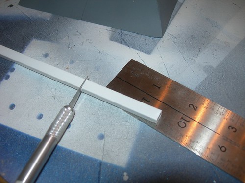
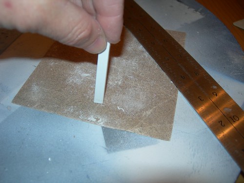
I cut a segment of the square tube of styrene channel approximately to length, and then lightly sanded the end to bring it down to the right size.
I fitted the segment into the slot, and glued it into place.
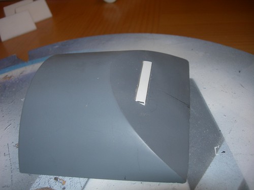
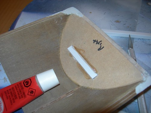
I repeated the process for the other ankle.
Once the glue has had time to dry, I will go back to the front side and trim off the front of the channel, flush with the surface of the sloped part of the ankle. Then, it will be ready for light filling and sanding.

No comments:
Post a Comment