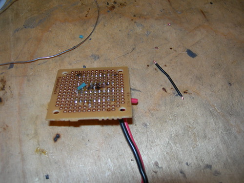
... tonight's effort, where I started soldering connections between pins.
Pin 16 on the PIC chip signals that a sound should be played on the CFSound III. But first we must convert the logic-high output from the PIC chip to a logic-low signal through the ULN2803A transistor array, by connecting pin 16 on the PIC chip to pin 1 on the transistor array using a short green wire. Pin 18 on the transistor array will take the inverted signal and pass it on as an input to the CFSound III, which requires a momentary ground to trigger a sound.
Next, I connected pin 9 on the ULN2803 and pin 5 on the PIC chip to ground. I used a black wire for that. Finally, I used a red wire to hook pin 14 on the PIC chip to what will be the positive battery connection.
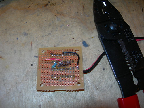
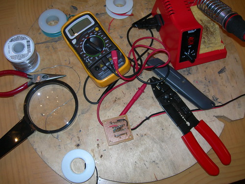
I used the continuity tester on my multimeter several times tonight, even though I barely soldered any connections. I did find two pins that were touching after I soldered the red wire, so I was able to fix that. Did I mention that I'm terrible at soldering?
I have an event tomorrow night, so this effort will probably be on hold until at least the weekend. Any competent person would have had this done in less than an hour, so this should take me another week or two...

No comments:
Post a Comment