The LEDs will be placed on some perfboard. I marked it up so that the 16 LEDs will be centered on it. I plan to use the exact same LED location and flashing pattern as on droid #1.

As was the case with droid #1's rear logics, I am using some scavenged PATA cable to wire the LEDs to the PIC flasher board.


I actually used my droid building notebook that I started back in 2005!!

In it, I noted the cross-stitch pattern I used, based on/copied from Mike Senna's original rear logics.

I pulled 9 strands of wire from the ribbon cable, and wired one strand for each pair of LEDs that will be powered by the eight circuit outputs. The ninth connection in pink is for the common connection that all the LEDs' cathodes will share.


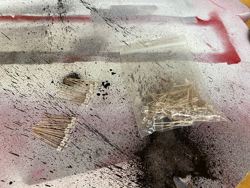
Next up, 16 LEDs from my bag-o-white-LEDs.

I placed them in the offset pattern that I used on droid #1.


I then cut down the LED legs.

Next, I solder-stitched all the LED cathodes together, utilizing the LED legs for the connections, and a short segment of wire for the U-turn on the right.

Next, I soldered all the data lines to the anodes of the top row of LEDs, and connected the common ground connection to the cathode bus that I created.

I then had to cross-stitch the top row of LEDs to the bottom row of LEDs, using the pattern from my notebook. Since I'm controlling 16 LEDs using only 8 outputs from the PIC flasher circuit, LEDs need to be paired up, but in such a way that it's not obvious that they are paired up.

Time to test! I applied power, and... nothing. No blinky.

I probably wired an LED backward. Well, maybe. Depending on which LED, I'd expect some LEDs to illuminate, until it reaches the backward LED. We'll see... tomorrow.

No comments:
Post a Comment