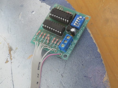
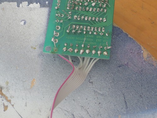
First, I needed to desolder the ribbon cable that connects the PIC Flasher circuit to the LED board. Yes, the old board really does look that bad.
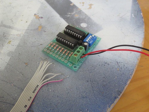
The new board anxiously awaits the ribbon cable.
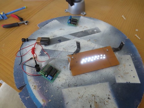
And it actually works(!).
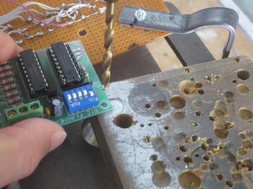
I needed to slightly widen the mounting holes on the board to accommodate a #6 nylon screw. I wish I had realized this before I put everything together.
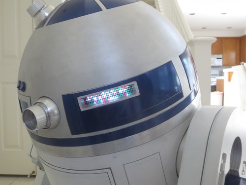
And finally, into the dome it goes. The cheesy transparency allows the 16 LEDs to at least look something like 108 LEDs. Kind of.

No comments:
Post a Comment