Yesterday, I left off having routed the lower portion of the inside of the dome base ring to allow room for the Rockler bearing. Today I raised the router bit to allow for full vertical clearance of the bearing into the dome (and then some).
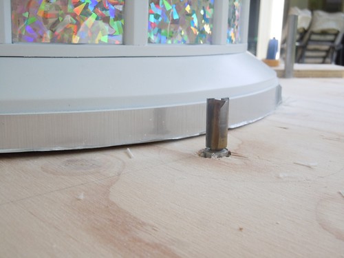
As was the case yesterday, this was an iterative exercise, where I reused the peg stop positions to route out a little more material at a time. The peg positions were chosen on a best-guess basis, with no real measurements taken.
The first stair step is from yesterday's work, with the router bit set to a lower position. The second stair step is from the first pass of the router from today's work, with the bit set at the higher position.
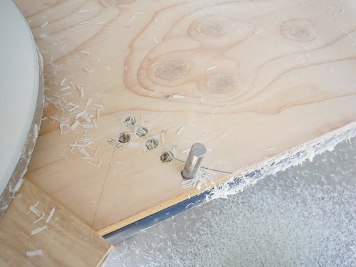
After six passes with the router bit raised to its new, higher position, the entire Rockler bearing fit into the dome vertically, with room to spare.

As luck would have it though, there is a problem. Normally the screws that slide through the dome ring fit just fine on an R2 dome. However, on this R5 dome, the screws don't have a good dome ring to fit through.
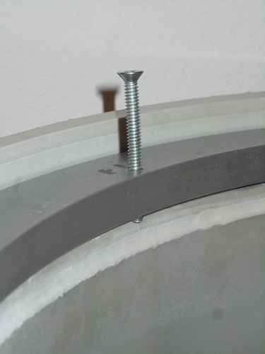
What to do?? Building a dome ring won't be of much help, as half of the screw would poke down into the neck area, and possibly poke through the outer surface of the dome.
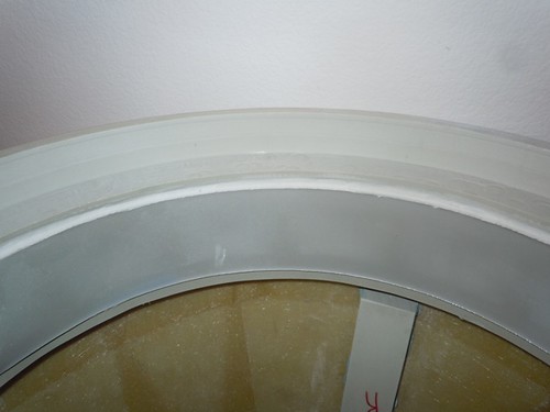
Mike came up with the idea of securing the screws to the dome itself, and have them point down, rather than have the the screws pointing up from the Rockler bearing. I think I've seen this idea used before, and I'll have to use it here.
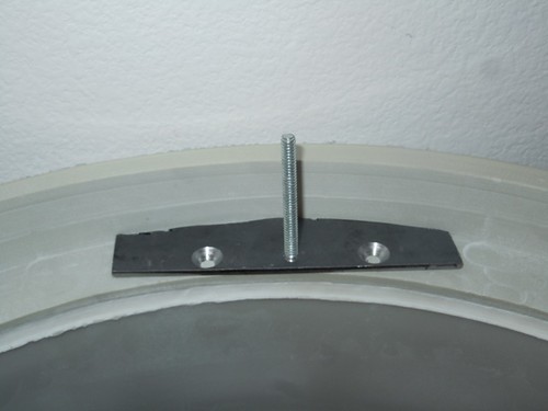
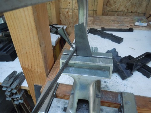
So, how to secure the screws to the dome? Mike suggested attaching segments of steel bar to the dome with screws and glue, and have the #10 screws that will point down be attached to the segments of steel bar. Here is a preview of a loose-fit of what I'm talking about.
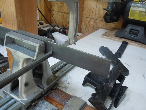
Time for another episode of "Cutting Lots of Steel with a Hacksaw," my least favorite form of entertainment.
First, I cut six segments of steel bar stock to a semi-arbitrary length. Mainly we're looking for a decent amount of surface area for when it will be bonded and screwed onto the dome.
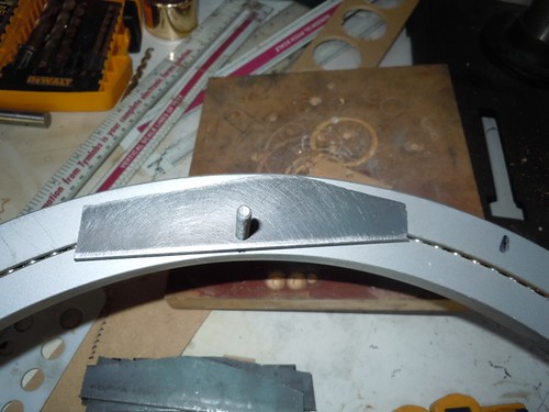
I traced the arc of the bearing onto the steel segment, so I'd know where I needed to do more trimming.
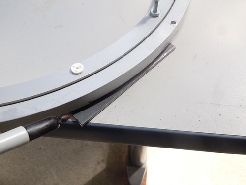
Without these extra cuts, the steel segments would bump into the inside perimeter of the dome, thereby forcing the inside edge of the bar into the dome drive wheel, and we don't want that.
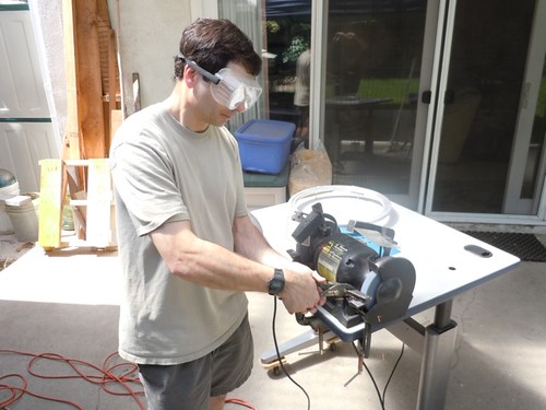
Some barely visible sparks on the grinder help clean things up. That looks like Michael McMaster's reflection in the glass, with the camera.
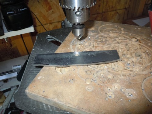
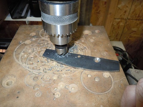
With 18 total cuts of steel out of the way, it was time to start drilling holes for the #10 dome screws.

Followed by countersinking.
Next, I drilled two more holes on each of the steel segments and countersunk them on the opposite side of the center hole, for the screws that will be used to help secure the segments to the dome. The plan is to use #10 1/2" wood screws, and glue.
And that's all I had time for today. Here are the six steel segments, loose-fitted.
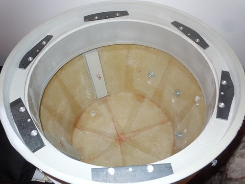
Returning to the picture I previewed earlier, the two holes on the left and right will have the #10 1/2" wood screws in them, while the center hole is home to the #10 screws that will slip through the Rockler bearing holes, with the bearing secured to the frame, but absent the usual screws that face upward.
Mike is busy getting his WALL•E ready for Maker Faire in the San Francisco Bay Area in a couple of weeks, so I'm planning to pause on this effort until he's done with that. Next steps will be to use the Rockler bearing itself as a template for where each of the six steel segments should be secured to the dome. We'll get there eventually.

2 comments:
Some serious modifying going on!! Keep up the good work :)
Thanks!
Post a Comment