I was determined to get it right this time. I started by making a paper template.


I translated the paper template to the cutting board I've been using for the ankle locks, and cut the piece to size.

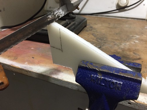

I then did a test fit. I'm ok with between a 1 and 2 mm gap between the foot shell and the bottom of the ankle lock. Here, the ankle lock is resting on the foot shell, so the gap is on top.

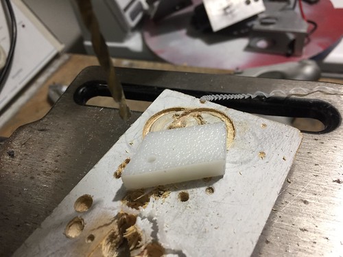
The next question is, where to drill the mounting hole? The hole has to be located such that a screw driver can reach around the motor. I (foolishly) convinced myself the upper left was the way to go.
But when I mounted the ankle lock and screwed it down, I found that I still couldn't quite reach around the motor. This shows the lock mounted, but not the motor being in the way.

So I had to drill a new hole on the opposite corner, which was accessible with a screwdriver.

I did a lot of test driving with this new ankle lock, and it really looks like it's going to work this time.