Friday, June 16, 2023

Finished Installing PIC Flasher-based Rear Logics on Droid #2

Today I wrapped up work on installing the PIC flasher-based rear logics on droid #2.

I stacked a pair of LED patterns printed on a transparency, and taped them together. I trimmed the corners to avoid interfering the mounting screws.


I then taped that to the aluminum rear logic surround.


Before going any further, I checked to make sure the LED patterns looked centered from the outside, and they did.


Next I reinstalled the rear logic electronics.


Finally, I powered up the dome and took a look.


With video:


Good enough for me, I'm calling this done. For now, at least.

Thursday, June 15, 2023

Printed Transparencies for Rear Logics for Droid #2

I had higher hopes for today, but all I ended up doing was printing and trimming the LED pattern for the rear logics, for the PIC flasher-based rear logics on droid #2.

I printed several of them on one transparency, because, why not? And I cut two of them out because I will be doubling up on them to make the colors look a bit deeper when the LEDs are shining through them.


I vow to get these installed tomorrow.

Monday, June 12, 2023

Prepped PIC Flasher Rear Logics on Droid #2 for Dome Installation

Today I worked on getting the PIC flasher circuit and LEDs ready for installation in the dome on droid #2.

First, I 3D-printed some standoffs with a length of 28mm, an inner diameter of 3.1mm, and an outer diameter of 15mm. These are for use with 3mm diameter screws that are 35mm in length. I wanted even longer screws and standoffs to put some distance between the LEDs and the rear logic surround, but this length should be okay.


The aluminum surround has six 3mm mounting holes, and I plan to use the four holes in the corners to mount the LED perfboard. I used the rear logic bezel from the JEDI logics as a template for where to measure and mark mounting holes.


I took the work over to the drill press and drilled the holes for the four corners.


I also need to mount the PIC flasher circuit itself to the perfboard. I am using #8 nylon screws, and I need to widen the mounting holes a little bit on the PIC flasher board.


Then I drilled the perfboard to accept the #8 nylon screws.


The screw head encroaches on the components in the corners, so I trimmed a little material from them.


And the reverse side.


Time to install this mess in the dome! I used the 3mm screws to secure things down.


Looks reasonably good.


All that's left is to print and cut the transparencies to size and tape those onto the rear logic surround. It turns out I don't have any transparencies on hand, so I need to get those and then wrap this up.

Saturday, June 10, 2023

Got LEDs on PIC Flasher Rear Logics Blinking for Droid #2

Today I fixed a couple of issues on the PIC flasher-based rear logics that I am wrapping up for droid #2. First, as I suspected, one LED was installed backward. As the "D" in LED stands for Diode, installing an LED backwards will prevent current from continuing on to the rest of the circuit. It just so happens that it was the last LED on the cathode bus, so that wasn't the only problem; had it been, I expect that only that single LED would not have illuminated. Instead, no LEDs were lit.

I used a multimeter to ring-out the board, and I realized that I failed to supply voltage to the transistor array that feeds the LEDs their power. The power terminal on the PIC flasher board has two voltage inputs, one for 9-12v to power the PIC chip and associated electronics (this goes through a 5v regulator), and a 9-45v supply to power the LEDs. As 9 volts are sufficient to power the LEDs, I simply needed to bridge the pins on the solder-side of the connector.


After fixing that and the LED issue, the circuit worked as expected.


I still have a little more work to do to get this installed in the droid.

Friday, June 09, 2023

Attached LEDs to PIC Flasher for Droid #2 Rear Logics

After dragging my feet on the rear logics update for droid #2, I finally got around to working on attaching the LEDs to the PIC flasher circuit I'll be using.

The LEDs will be placed on some perfboard. I marked it up so that the 16 LEDs will be centered on it. I plan to use the exact same LED location and flashing pattern as on droid #1.


As was the case with droid #1's rear logics, I am using some scavenged PATA cable to wire the LEDs to the PIC flasher board.


I actually used my droid building notebook that I started back in 2005!!


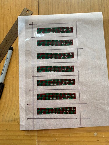
In it, I noted the cross-stitch pattern I used, based on/copied from Mike Senna's original rear logics.


I pulled 9 strands of wire from the ribbon cable, and wired one strand for each pair of LEDs that will be powered by the eight circuit outputs. The ninth connection in pink is for the common connection that all the LEDs' cathodes will share.


Next up, 16 LEDs from my bag-o-white-LEDs.


I placed them in the offset pattern that I used on droid #1.


I then cut down the LED legs.


Next, I solder-stitched all the LED cathodes together, utilizing the LED legs for the connections, and a short segment of wire for the U-turn on the right.


Next, I soldered all the data lines to the anodes of the top row of LEDs, and connected the common ground connection to the cathode bus that I created.


I then had to cross-stitch the top row of LEDs to the bottom row of LEDs, using the pattern from my notebook. Since I'm controlling 16 LEDs using only 8 outputs from the PIC flasher circuit, LEDs need to be paired up, but in such a way that it's not obvious that they are paired up.


Time to test! I applied power, and... nothing. No blinky.


I probably wired an LED backward. Well, maybe. Depending on which LED, I'd expect some LEDs to illuminate, until it reaches the backward LED. We'll see... tomorrow.