Sunday, January 31, 2021

Wired Up New Speed Controller for Droid #2

Today I worked on wiring up the new Sabertooth 2x32 speed controller for droid #2, and corrected a bit of a mistake from yesterday.


The outer pairs of wires are for each of the two foot motors. The center pair of wires is for the main power to the speed controller from my 12 volt batteries.


Channels 1 and 2 on the receiver are throttle and steering.


I only want the signal wire to attach to the speed controller. Grounds are common, and are internally sourced from the main battery. The 0v and 5v connections on the speed controller are outputs, not inputs. They can supply power to the receiver, but I already have a battery elimination circuit doing that job.


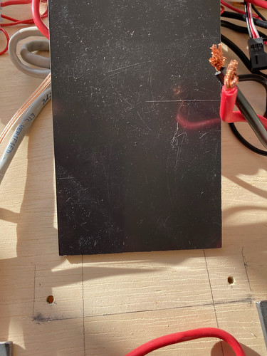
And now to my mistake. I should have paid more attention to those indentations at the bottom of the board, rather than just the marks. These show where the PVC rectangle mounting piece I cut yesterday really should have been located.


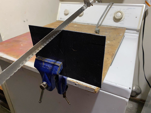
Okidoke, I need to recut and redrill the PVC rectangle. I can deal with that.


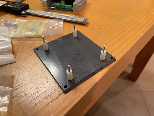
Ok, now things will fit when I slide this board into the droid. The screw locations won't run into the center leg now.


Hmm... the wiring doesn't seem much neater.

Saturday, January 30, 2021

Started Speed Controller Update for Droid #2

Holy moly, it's been forever since I've had anything to report here. That's what a pandemic will do, I suppose. Well, it's time to take care of a few to-do items.

First on the list, updating the speed controller on droid #2. I updated droid #1 with a Sabertooth 2x32 speed controller back in April 2018, and now it's droid #2's turn. In both cases, the speed controller being replaced is the Vantec RDFR23. With any luck, maybe I'll be able to make the wiring a bit neater while I'm at it...


Out with the old.


Before bringing in the new, I need to cut a mounting piece of flat PVC. Dimension Engineering recommedns leaving some room for air flow for ventillation, so I plan to mount the speed controller to the PVC, and use some nylon standoffs to mount to the electronics board.

First I need to cut the PVC to size. I want this to be wide enough that the mount points for the screws don't run into the center leg, which leads up into the body and on which the electronics board rests. So I want to cut the PVC to be wider than the center leg outline on the electronics board. That's the idea, at least...


With the PVC cut to size and drilling points marked, it was time to drill the mounting holes.


And with the holes drilled, I can use this piece as a template for drilling matching holes in the electroncs board.


Next, I can use the speed controller mounting holes to drill matching holes in the PVC.


With that done, I can do a test-fit on the electronics board. In go the standoffs.


And the test fit on the board.


Still lots to do, but it's a start.