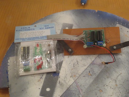
Long ago I ordered a spare PIC Flasher kit from Carls' Electronics. Time to bust that out and replace the old board.
I soldered the components in place, one-by-one. There aren't that many, although there are a couple of 18-pin socketed DIPs. Probably around 80 solder joints in all.
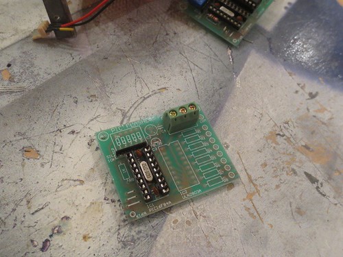
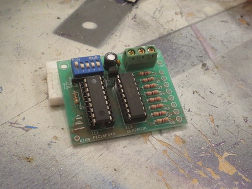
And done with the soldering. The PIC chip and transistor array still need to be inserted in their sockets.
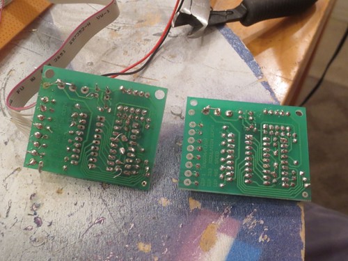
I'm still not great at soldering, but I've come a long way since 2006. I intentionally left some of the leads long on the old board on the left, thinking that if I had to pull the part out, it would be easier to reuse it later. Bad idea on many levels.
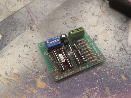
I inserted the chips and gave it a quick test with an LED, and it works!
Tomorrow I'll solder on the ribbon cable that links to the real LEDs.


No comments:
Post a Comment